
Page 45 - IJB-6-4
P. 45
Celik, et al.
A specification is constructed from a metric and a
Total value 100 99.996 1051.571 1053.775 31.886 0 value , which correspond to a specific function
[18]
of the product. A function can have one or more
metrics and values. The final list of specification
objectives in relation to the TFA results is given
F10 13.273 12.315 176.173 163.457 0.972 26.17 in Table 5.
The analysis of alternative designs was
undertaken using TFA instruments to select the best
F9 9.455 8.312 89.397 78.59 1.352 21.989 candidate for further investigation. The selection
criteria and their weights were set by the TFA
team. As shown in Table 6, Candidate 5 obtained
F8 9.455 9.236 89.397 87.326 0.057 4.516 the best total score, best ensuring the functional
characteristics required.
2.6 Prototyping
F7 10.909 7.758 119.006 84.632 10.073 69.247 Once the first functional prototype of a detail design
is exhibited, prototype testing can be performed
to validate the proposed design solution. If the
F6 7.091 5.849 50.282 41.475 1.58 17.825 design solution cannot meet the required design
Functions until a satisfactory desired solution is reached. At
objectives, the product design process is repeated
F5 11.091 10.16 123.01 112.685 0.911 21.167 this stage, it is possible to undertake both virtual
prototype and physical prototype-based design
verifications.
12.545 15.763 157.377 197.747 10.187 -80.08 2.7 Virtual prototyping: Finite element analysis
F4 (FEA) verification
After approval of the design details of Candidate
F3 12 13.793 144 165.516 3.125 -42.428 5, a 3D parametric solid model was constructed in
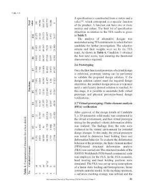
Table 4. Computational elements for a face shield.
the virtual environment, and then virtual prototype
testing for the product’s elastic deformation ability
F2 6 6.958 36 41.748 0.894 -11.345 was realized. The findings from the tests were
evaluated in the virtual environment for potential
design changes. In this study, the virtual prototype
F1 8.181 9.852 66.929 80.599 2.735 -27.06 was tested to determine head holding force and
deformation behavior. To evaluate the deformation
behavior of the prototype, the finite element method
(FEM)-based structural deformation analysis
Calculated elements ANSYS Workbench FEM-based commercial code
(FEA) was carried out. The structural module of the
was employed for the FEA. In the FEA scenarios,
head wearing and head holding positions were
xi * yi
simulated. The FEA was set up using assumptions
xi 2
S’
of a linear static loading and homogeneous, linear
yi
xi
S
isotropic material model. At the meshing operation,
No. 1. 2. 3. 4. 6. 7. a curvature meshing strategy was utilized and the
International Journal of Bioprinting (2020)–Volume 6, Issue 4 41