
Page 468 - IJB-10-6
P. 468
International Journal of Bioprinting Stress prediction in 3D-printed scaffolds
Table 2. Properties of hydroxyapatite (HAP) mesh, and smoothing the model, it was ensured that no
sharp structures would exist on the model’s surface. Lastly,
Parameter Specification a quadratic tetrahedral mesh was created. The model, with
3
Density (g/cm ) 3.16 a partitioned volume mesh, was exported as an STL file
Elastic modulus (MPa) 300 and saved for subsequent FEA.
Poisson’s ratio 0.3 The solver setup used artificial time-stepping control,
Tensor property Anisotropy with a termination time for solving set at 30 s, corresponding
to the practical compression test at a speed of 5 mm/min,
rigid bodies were modeled at the upper and lower ends and the time step was set at 0.1 s, with 300 iterations. The
of the scaffold model, simulating the weights and steel equivalent stress of all scaffolds was evaluated.
plates used in compression experiments. The lower rigid
body was fixed, and a downwards displacement boundary 2.7. Statistical analysis
condition of 2.5 mm was applied to the upper rigid body. The results were presented as mean ± standard deviation,
and statistical analysis was performed using SPSS 22.0
The displacement in other directions was set to 0 mm. The software. Two-way analysis of variance (ANOVA) was used
calculation time was set to 30 s and the compression speed to evaluate the differences between groups. In statistics, *
to 5 mm/min. The contact between the scaffold and the denotes p < 0.05, ** denotes p < 0.01, and *** denotes p <
rigid bodies was set as bonded contact. 0.001; p < 0.05 is considered statistically significant.
For mesh partitioning, in the theoretical model,
tetrahedra meshes with a size of 0.2 mm were selected. 3. Results and discussion
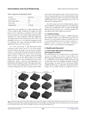
For the reconstructed model, after converting the surface 3.1. Macroscopic deformation of 3D-printed
mesh to a solid mesh following the method described hydroxyapatite scaffolds
below, tetrahedra meshes with a size of 0.2 mm were also The scaffold used for bone repair should accurately match
selected (Figure 2). Briefly, automatic mesh partitioning the size and shape of the defect to ensure that it can
was conducted on the 3D solid model in STL format effectively support and repair the damaged tissue. However,
using 3-matic software. After completing the surface mesh the scaffold will undergo significant deformations during
partitioning, quality inspection and adjustment were the preparation process, especially during the drying and
performed on the generated mesh. Following mesh repair, sintering stages. To ensure that the final porous scaffold
further manual mesh partitioning was performed on the could fit the defect site, we explored the shape characteristic
model. By adjusting the mesh size, optimizing the surface changes of the scaffold during the preparation process.
Figure 2. Reconstruction model mesh division and local mesh characteristic diagram. (a) Mesh division effect of the reconstructed models. (b) Local mesh
distribution characteristics of the reconstructed scaffold model at 90° after sintering. Areas with irregular structures had denser meshes. Scale bar: The scale
bar was divided into four sections, with a total length of 20 mm and each section representing 5 mm.
Volume 10 Issue 6 (2024) 460 doi: 10.36922/ijb.4460