
Page 472 - IJB-10-6
P. 472
International Journal of Bioprinting Stress prediction in 3D-printed scaffolds
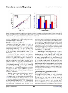
Figure 6. Mechanical properties of 3D-printed hydroxyapatite (HAP) scaffolds. (a) Stress–strain curve of sintered scaffolds, displaying a linear trend. (b)
Mechanical properties of scaffolds at different angles (n = 3); blue color denotes compressive strength and red color denotes compression modulus. The 90°
scaffold exhibits the highest compressive strength and compression modulus. ***p < 0.001.
based on scanning a printed scaffold, which could better protruding regions of the scaffold. These results are related
reflect the true state of the scaffold. to the uneven surface of the printed scaffold due to material
deposition during the printing process. The uneven surface
3.4.2. Stress distribution predictions of printed scaffolds, with areas around the 90° corners and
Corresponding equivalent stress nephograms (Figure 8) edges higher than the central region, experienced greater
were obtained from the FEA results of the theoretical
model and reconstructed model. By comparing the results stress, and stress was more concentrated at the edges. The
of the two analysis methods, it was found that there were 60° and 45° scaffolds had more printing defects, with stress
significant differences in the stress distribution obtained concentrated at protruding parts.
by the reconstructed model compared to that of the Compression tests were conducted on the scaffolds to
design model. obtain the scaffold fracture state diagram (Figure 9). It was
According to the stress nephogram obtained from observed that the fracture points of the 90° scaffold were
the theoretical model analysis (Figure 8a), the stress mainly distributed along the peripheral edges, while the
distribution within the scaffold was highly regular, with all 60° and 45° scaffolds fractured at the protruding vertices,
stress concentrations occurring at the intersection points. consistent with the stress concentration areas predicted
This distribution characteristic can be attributed to the by the reconstruction model. This demonstrated that
orderly structure of the design model and uniformity in the reconstructed model can accurately reflect the stress
the positions and sizes of the pillars, leading to even stress concentration within the scaffolds, improving the accuracy
transfer and distribution. As the main factors supporting of the analysis. It was noteworthy that when the edge of
the scaffold and withstanding pressure, the number and the scaffold fractured, its central region remained intact,
alignment of the struts directly affect the mechanical which further proved the influence of stress concentration
properties of the scaffold, suggesting that more and better- on scaffold failure.
aligned pillars can better withstand pressure and improve
mechanical performance. 3.5. Early prediction of stress distribution in
However, there were significant differences between hydroxyapatite scaffolds
the stress distribution obtained from the FEA using the Using the reconstructed model for FEA can effectively
reconstructed model and the results of the theoretical model predict the internal stress distribution of the scaffold
(Figure 8b). The predictions of the reconstructed model without additional costs. The preparation process of
revealed pronounced stress concentration areas, with the 3D-printed HAP scaffolds is cumbersome, requiring
90° scaffold mainly experiencing stress concentrations further drying and sintering after printing, which
at the edges, while the 60° and 45° scaffolds exhibited leads to a relatively long cycle. This paper analyzes the
more disordered concentration areas, primarily in the equivalent stress nephograms of scaffolds in different states
Volume 10 Issue 6 (2024) 464 doi: 10.36922/ijb.4460