
Page 474 - IJB-10-6
P. 474
International Journal of Bioprinting Stress prediction in 3D-printed scaffolds
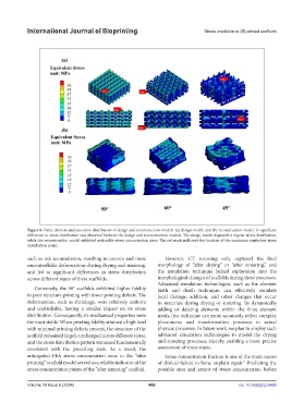
Figure 8. Finite element analysis stress distribution of design and reconstruction models: (a) design model; and (b) reconstruction model. A significant
difference in stress distribution was observed between the design and reconstruction models. The design model displayed a regular stress distribution,
while the reconstruction model exhibited noticeable stress concentration areas. The red mark indicated the location of the maximum equivalent stress
distribution point.
such as ink accumulation, resulting in uneven and more However, CT scanning only captured the final
uncontrollable deformations during drying and sintering, morphology of “after drying” or “after sintering,” and
and led to significant differences in stress distribution the simulation technique lacked exploration into the
across different states of these scaffolds. morphological changes of scaffolds during these processes.
Advanced simulation technologies, such as the element
Conversely, the 90° scaffolds exhibited higher fidelity birth and death technique, can effectively simulate
in pore structure printing with fewer printing defects. The local damage, addition, and other changes that occur
deformations, such as shrinkage, were relatively uniform in materials during drying or sintering. By dynamically
and controllable, having a smaller impact on its stress adding or deleting elements within the finite element
distribution. Consequently, its mechanical properties were mesh, this technique can more accurately reflect complex
the most stable. When printing fidelity attained a high level phenomena and transformation processes in actual
with minimal printing defects present, the structure of the physical processes. In future work, we plan to employ such
scaffold remained largely unchanged across different states, advanced simulation technologies to model the drying
and the stress distribution pattern remained fundamentally and sintering processes, thereby enabling a more precise
consistent with the preceding state. As a result, the assessment of stress states.
anticipated FEA stress concentration zone in the “after Stress concentration fracture is one of the main causes
printing” scaffold model served as a reliable indicator of the of clinical failure in bone implant repair. Predicting the
8
stress concentration points of the “after sintering” scaffold. possible sites and extent of stress concentration before
Volume 10 Issue 6 (2024) 466 doi: 10.36922/ijb.4460