
Page 161 - IJB-7-3
P. 161
Al-Tamimi
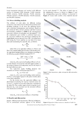
linear hexahedral elements and meshed with different by the mesh density [16,18] . The effect of mesh size on
number of elements (5000 elements, 10,000 elements, the optimization process is shown in Figure 3 and
25,000 elements, 50,000 elements, 75,000 elements, the corresponding equivalent stiffness is presented in
100,000 elements, 250,000 elements, 350,000 elements, Figure 4. Coarse mesh results in less material removal
and 400,000 elements).
3.4. Stress shielding analysis
The stiffness of each plate, for different loading
conditions, is the main criteria to determine possible stress
shielding problems. In all cases, the optimized plates
were considered homogeneous and isotropic. Based on
the numerical finite element analyses and their loading
and boundary conditions in Table 2, the corresponding
equivalent stiffness of each plate was determined . For
[12]
the compression case (similar to combined load case),
the equivalent stiffness was calculated considering the
longitudinal reaction uniaxial force (RF ) in kilonewton
xx
(kN) along the X-axis applied on one end of the bone
plate and constraining the opposite side, as follows:
RF
K Te = D xx xx (3.1)
where KTe is the equivalent stiffness in kN/mm and
Dxx is the resulted displacement in mm. In the bending case,
the equivalent bending stiffness was calculated according to
the following equation (British Standard 1991) :
[15]
( 4h + 2 12hς ς + 2 ) Sh
K = 24 (3.2)
B
where K is the equivalent bending stiffness in N.m ,
2
B
h is the distance between the load and support points, is
the distance between the load points, and S is the slope of
the load-deflection curve.
The equivalent elastic bending modulus was
measured as follows (ASTM Standard 2017) :
[17]
3
/
E = 0.17L S bd 3 (3.3) Figure 3. Mesh dependency - plate redesigns for different number
B
of elements.
where E is the equivalent bending elastic modulus
B
in GPa, L is the support span, b is the plate’s width, and d
is the plate’s thickness.
For the torsion case, the equivalent stiffness was
determined considering the reaction moment across the
X-axis (T ) applied on one end of the plate, constraining
xx
the other end. The resulted angle of twist along the X-axis
direction (φ ) was recorded and the torsional stiffness
xx
was determined as follows:
T
K = xx (3.4)
Tr
ϕ xx
where K is the torsional stiffness in Nmm/Rad.
Tr
4. Results and discussion
Despite utilizing mesh-dependency filtering techniques,
TO in commercial software appears to be affected Figure 4. Equivalent stiffness values as a function of mesh size.
International Journal of Bioprinting (2021)–Volume 7, Issue 3 157