
Page 159 - IJB-7-3
P. 159
Al-Tamimi
independent filtering and sensitivity filtering to prevent screw holes, six-screw holes, and eight-screw holes) were
checkerboarding) along the design domain. designed using Solidworks (Dassault Systèmes, France)
with a length of 180 mm, width of 14 mm, and thickness
3. Simulation and optimization of 5 mm (Table 1). Abaqus (Dassault Systèmes, France)
was used to perform the TO and finite element analysis.
3.1. Initial design domains Plates were considered to be made with Ti-6Al-4V (120
The DePuy Synthes narrow LCP, commonly used for the GPa of Elastic Modulus and 0.3 of Poisson’s ratio).
treatment of long bones such as humerus, femur, and tibia, Finite element meshes were created using eight-node
was considered as a reference design. Three plates (four- linear hexahedral elements and approximately 400,000
elements were considered. Different mesh densities were
also considered for the mesh dependency study.
Design domain
3.2. Loading and boundary conditions
Considering possible physiological events, the plate
Material Definition
(E,V, ρ) was subjected to four types of loadings: compression,
bending, torsion, and a combination of these loads
that mainly occur on the screw holes and the mid-
Domain discretisation plate (Table 2). Compression corresponded to a static
by finite element compressing force along the X-axis (the axis along the
length of the plate) applied on both far-end sides of the
plate and constraining the six nodes on the two opposite
Finite element analysis middle faces of the plate in all directions and rotations
(d =d =d =r =r =r =0), symbolized by an encastre
y
x
z
y
z
x
constraint. Bending corresponded to a static four-point
bending test applied on the plate according to the bone
Objective function (ε) [15]
Constraints (V) fixation plate testing standards (ISO 9585:1990) . The
two loading points were separated with a distance of
two screw holes and at least one screw hole between the
load and support point. The support points constrained
Density initialization the bone plate from moving across the Z-axis (dx=dy=0,
dz≠0) (the axis crossing the thickness of the plate),
symbolized by a red-colored pin constraint. An additional
Sensitivity two constraints were used to ensure stability in the X and
breakdown Y axis (dx=dy≠0, dz=0) (the axis along the width of the
plate) during loading, symbolized by an orange color pin
constraint. Torsion corresponded to static moment acting
Filtering along the X-axis on one end and constrained (i.e. pinned)
sensitivity/techniques on the other end of the plate (dx=dy=dz=0), symbolized
by an orange color pin constraint. Combined load was
the combination of compression, bending, and torsion,
Design’s density considering the constraints of the compression test. It is
updating important to note that SIMP method was not sensitive to
the load magnitude when the compliance for a given load
was minimized.
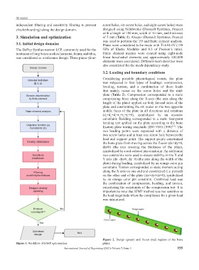
Problem No
converged??
Yes
Optimised
design End
Figure 2. Design (green) and frozen (red) regions of the bone
Figure 1. Workflow of SIMP optimisation. plates.
International Journal of Bioprinting (2021)–Volume 7, Issue 3 155