
Page 163 - IJB-8-1
P. 163
Lin, et al.
that longer mandibles have higher bending stress (σ) and
Patient with are more prone to damage. When calculating the V value,
mandible defect
the height and thickness values should be preceded by a
negative sign, indicating that σ is negatively correlated
with HB and TB. A large V value indicates a dangerous
mandible structure (worst case) because the mandible is
CT image reconstruction
and measuring subjected to more bending stress (σ). The V value result
segmental bone dimension was found from the range between 13.71 and −25.74,
meaning that if the V value of another defected mandible
falls in this range, it can be repaired using the design
criteria proposed in this study.
NO Due to the size and position of the internal supporting
Calculating Other surgical approach
V value beams for various reconstructed implants, parametrically
design using the corresponding patient-specific segmental
Fall into range of V value bone thickness, height, and teeth position, patient-specific
reconstructed implants with lightweight structure can
be obtained directly according to our developed design
Confirmation of defect
bone segment criteria and exported for AM (Table 7). The internal
support beam design for segmental reconstructed implant
C was described in section 2.3. The internal two support
beams of reconstructed implant B were oblique cylinders
Internal supporting beam
and beam 1 extended from the implant surface at the
design according to the
design criteria 2 premolar axis to the lingual side with a quarter of the
nd
bone height. Beam 2 extended from the end of beam 1
to the buccal side with the bottom of the implant at the
st
STL file export for distal 1 molar margin. In addition, there were four beam
AM manufacturing
supporting beams within the reconstructed implant A+B,
beams 1 and 4 were cylinders from lingual to buccal sides
with positions at the 2 premolar center with a height of
nd
(BB /4+a/2) at the intersection of 1/2 AB and BB /4
Clinical surgery H RH H
axis, respectively. Beams 2 and 3 were oblique cylinders,
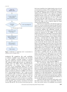
Figure 4. Flowchart of mandibular defect reconstruction in with beam 2 extended from the top surface turning
adherence with our design criteria. point of the implant at the lingual side to the buccal side
with the bottom surface of the implant at the axis of the
2 molar and beam 3 extended from the half of AB of
nd
mechanical SE comparison, this study establishes the top surface of the implant to the buccal side at the
RH
an effective mandible image database and identified implant turning point. Other internal support beam bone
the worst mandible structural strength to perform segments for B+C and B+C+B can then be defined using
segmental lightweight structure optimization analysis. a combination of B and C bone segments (Table 7).
The segmental lightweight structure can withstand the The reconstructed implant design based on our
occlusal force for further dental implant/prosthesis criteria must consider the upper space to allow further
considerations. The design criteria developed in bone grafts to have dental implants with prosthesis. The
this study can be subsequently applied to the clinic thickness must also consider the space for soft-tissue flap.
according to Figure 4. The patient’s mandible segmental However, a dental implant with prosthesis still cannot be
dimension characteristics can be measured using CT designed and manufactured together in this study because
images according the definition in Table 1 and obtained it easily causes bacterial infection if the soft tissue cannot
the V value through Equation 1. The V value was used completely cover the metal implant . The dental implant
[22]
as a simplified value to express the mandible structural with prosthesis can be planned and printed before surgery
strength. Its positive and negative values were derived if the contact area between the mucosal tissue and the
from the bending stress of the mandible. When the metal can be effectively treated antibacterial medicines or
bending stress (σ) of the cantilever beam was calculated, the relevant AM material is developed.
a positive correlation was found between σ and the LB At present, relevant research that can be used to verify
of the mandible, and a negative correlation was found the results of the current study is unavailable. However,
between HB and TB. The cantilever beam theory proves there were similar studies on mandibular reconstruction
International Journal of Bioprinting (2022)–Volume 8, Issue 1 149