
Page 26 - IJB-8-1
P. 26
Multi-Layer Deformable Design for Prosthetic Hands
to the surface model. We placed landmarks on the surface Before 3D printing the bones, we also put holes at
model to determine the positions, orientations, and sizes of the ends of them so that it could easily connect the bones
bones. As the bones have relatively fixed proportions and with rubber bands as ligaments (refer to Figure 3 for
connections [29,30] , we adjusted the surface model to make it the details). Unlike the previous method that requires
[27]
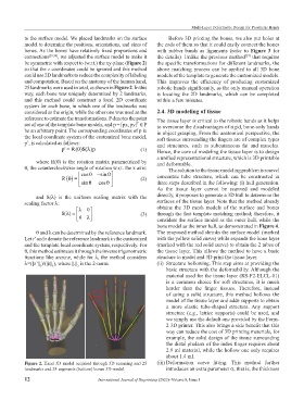
be symmetric with respect to (w.r.t.) the xy-plane (Figure 2) the specific transformations for different landmarks, the
so that the z coordinates could be ignored and this method above matching process can be applied to all 3D bone
could use 2D landmarks to reduce the complexity of labeling models of the template to generate the customized models.
and computation. Based on the anatomy of the human hand, This improves the efficiency of producing customized
25 landmarks were used in total, as shown in Figure 2. In this robotic hands significantly, as the only manual operation
way, each bone was uniquely determined by 2 landmarks, is locating the 2D landmarks, which can be completed
and this method could construct a local 2D coordinate within a few minutes.
system for each bone, in which one of the landmarks was
considered as the origin, while the other one was used as the 2.4. 3D modeling of tissue
reference to estimate the transformations. P denotes the point The tissue layer is critical to the robotic hands as it helps
set of one of the template bone models, and p = [px, py] ∈ P to overcome the disadvantages of rigid, bone-only hands
T
be an arbitrary point. The corresponding coordinates of p in in object grasping. From the anatomical perspective, the
the local coordinate system of the customized bone model, soft tissues surrounding the fingers are of complex types
p’, is calculated as follows: and structures, such as subcutaneous fat and muscles.
p' R= ()θ S()λ p (1) Hence, the core of modeling the tissue layer is to design
a unified representational structure, which is 3D printable
where R(θ) is the rotation matrix parametrized by and deformable.
θ, the counterclockwise angle of rotation w.r.t. the x axis: The solution to the tissue modeling problem is a novel
cosθ − sinθ concentric tube structure, which can be constructed in
R θ () = (2)
sinθ cosθ three steps described in the following: (i) hull generation.
As the tissue layer cannot be scanned and modeled
and S(λ) is the uniform scaling matrix with the directly, it proposes to generate a 3D hull to determine the
scaling factor λ: surfaces of the tissue layer. Note that the method already
λ 0 obtains the 3D mesh models of the surface and bones
S( )λ = (3) through the fast template matching method; therefore, it
0 λ considers the surface model as the outer hull, while the
bone model as the inner hull, as demonstrated in Figure 4.
θ and λ can be determined by the reference landmark. The proposed method shrinks the surface model (marked
Let r’ and r denote the reference landmark in the customized with the yellow solid curve) while expands the bone layer
and the template local coordinate system, respectively. For (marked with the red solid curve) to obtain the 2 tubes of
θ, this method estimates it through the inverse trigonometric the tissue layer. This allows the method to have a basic
functions like arcsine, while for λ, the method considers structure to model and 3D print the tissue layer.
λ=(||r’|| )/(||r|| ), where ||.|| is the 2-norm. (ii) Structure hollowing. This step aims at providing the
2
2
2
basic structure with the deformability. Although the
material used for the tissue layer (RS-F2-ELCL-01)
is a common choice for soft structures, it is much
harder than the finger tissues. Therefore, instead
of using a solid structure, this method hollows the
model of the tissue layer and adds supports to obtain
a more elastic tube-shaped structure. Any support
structure (e.g., lattice supports) could be used, and
we simply use the default one provided by the Form-
2 3D printer. This also brings a side benefit that this
way can reduce the cost of 3D printing materials, for
example, the solid design of the tissue surrounding
the distal phalanx of the index finger requires about
2.9 ml material, while the hollow one only requires
about 1.4 ml.
Figure 2. Hand 3D model acquired through 3D scanning and 25 (iii) Deformation curve fitting. This method further
landmarks and 24 segments (bottom) bones 3D model. introduces an extra parameter σ, that is, the thickness
12 International Journal of Bioprinting (2022)–Volume 8, Issue 1