
Page 76 - IJB-8-1
P. 76
AJ P of Bioelectrical Devices
®
A A
B
Figure 8. Printing of the device: on (A) glass substrate and (B)
NTE substrate. B
for a longer period of time (2 h against 8 min) at 150°C.
The results confirmed the previous observations, showing
a drastic cytotoxic ink behavior already after 24 h, with
no value detected at the following points of 48 h and
120 h (Figure 7D). As such, the printed PEDOT: PSS ink
is considered cytotoxic for NSCs.
To verify whether this ink behavior is related to a
dose-dependent and/or sintering condition, additional
indirect cell viability assays were carried out on
nanometric spin-coated PEDOT: PSS samples, and at six
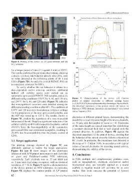
different curing conditions (150°C for 8, 60, and 120 min, Figure 9. Characterization of the device: (A) Contour
and 200°C for 8, 60, and 120 min). Figure 7E indicates profile of printed electrodes at different printing layers
that non-significant variations were detected among the n = (5, 20, 30, 40, 50), showing the potentiality of reaching ca. 30 µm with n 40;
different annealing conditions after 48 h. The conditions at (B) Electrical impedance of the printed circuit (40 layers) on
Parylene-C NTE substrate. Impedance (Ω) and phase (°) are plotted
150°C and 120 min were then taken as reference settings versus frequency (Hz).
for the preparation of the next spin-coated samples, and
the ATP was tested up to 120 h. The results, shown in electrodes at different printed layers, demonstrating the
Figure 7F, confirm the hypothesis of a dose-dependent possibility to reach the same height of the micro-channels,
behaviour of the ink. Despite a significant reduction of the ca. 30 µm, with the number of layers n ≥ 40. Electrodes
cellular viability at 48 h with respect to the plastic control
(40.61% less), the biocompatibility of the nanometric of the same height are indeed important for establishing
spin-coated films was considered acceptable, resulting in a constant electrical field that is well aligned with the
29.38% less biocompatibility than the plastic control at channel direction. In addition, Figure 9B depicts the
120 h. electrical impedance of the printed device, showing that
the behavior of the circuit correctly follows a theoretical
3.3. Target application RC circuit. In particular, the impedance was detected in
the range of 1 – 2 kΩ at 1 kHz, in accordance with typical
The printing strategy depicted in Figure 5C was values of neural electrodes for detecting neural activity,
ultimately applied to realize the target application. demonstrating the validity of the device.
Figure 8A and B show images of the prototypes
fabricated with AJ P printed interconnects and electrodes 4. Conclusions
®
on glass and Parylene-C-coated NTE substrates,
respectively. Each electrode was ca. 33 µm thick and In NTE, multiple and complementary guidance cues,
ca. 2 mm wide (including overspray), with an electrical such as topographical, electrical, mechanical and/or
resistance, R = 16 Ω. Figure 9 reports a characterization biochemical ones, are typically applied on a neural
of the device printed on NTE substrates. In particular, scaffold to regulate neural cell activities for in vitro
Figure 9A displays the contour profile of AJ printed studies. This work concerns the potential of Aerosol
®
62 International Journal of Bioprinting (2022)–Volume 8, Issue 1