
Page 120 - IJB-8-2
P. 120
Microstructured Calcium Phosphate Ceramics Scaffolds by Material Extrusion
filaments by pushing the plunger down, and the plunger Alternatively, elective pre-treatment in a 200°C oven for
speed was measured. The printer stage moved in the –x 4 h may be performed before detaching the print from
direction at the printing speed v. To print the first layer, the the substrate. The green parts underwent debinding at
nozzle tip was set at 0.6 mm (z ) above the print substrate. 500°C for 2 h and calcination at 900°C for 6 h in a box
1
The nozzle tip moved up by 0.5 mm (z ) every subsequent furnace (Nabertherm, Germany) using a heating ramp of
2
layer. A spirit level was used to ensure the print substrate 5°C/min. The samples were left to cool in the furnace
was level. The setup is shown in Figure 1 and the printing to prevent cracking during shrinkage. To determine the
parameters are described in Table 1. crystallographic phase transformation of the CaP after
When building structures taller than 3 mm, a hot calcination, the material was crushed into powder and
plate may be secured on the printer stage directly under analyzed by XRD using the same procedure as previously
the print substrate to enable quick drying of the water- described in section 2.1.
based ink during printing. The print substrate surface was
heated to 85 – 95°C. 2.6. Characterization of the prints
2.5. Post-processing of 3D printed parts and Cross-section surfaces of calcined parts exposed by brittle
chemical characterization fracture were observed under thermionic SEM (JEOL
5500LV) after coating with gold. Alternatively, calcined
The printed parts were left to dry in ambient conditions parts were embedded in resin and polished to examine
overnight before detaching them from the gypsum the microstructure under the SEM. The microplatelet
substrate from one edge by sliding in a sharp blade. orientations in the prints were determined by image
analysis using ImageJ v1.53g.
A B
3. Results and discussion
3.1. 3D printing approach
Our 3D printing approach (Figure 2) utilizes CaP
microplatelets of high aspect ratio suspended in an
aqueous slurry, which is extruded onto a porous water-
absorbent substrate for drying and consolidation. The
bioceramic chosen in the water-based ink is brushite
(CaHPO ·2H O), a type of CaP also known as dicalcium
2
4
phosphate dihydrate (DCPD). Brushite microplatelets
can be synthesized in scalable quantities and yield a
bioresorbable material, calcium pyrophosphate, after
calcination (Supplementary file: Section 1.1 for
[32]
details about the crystallographic phase). Here, the
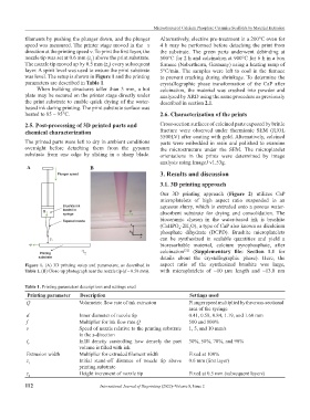
Figure 1. (A) 3D printing setup and parameters, as described in aspect ratio of the synthesized brushite was large,
Table 1. (B) Close-up photograph near the nozzle tip (d = 0.58 mm). with microplatelets of ~10 µm length and ~13.8 nm
Table 1. Printing parameters descriptions and settings used
Printing parameter Description Settings used
Q Volumetric flow rate of ink extrusion Plunger speed multiplied by the cross-sectional
area of the syringe
d Inner diameter of nozzle tip 0.41, 0.58, 0.84, 1.19, and 1.60 mm
f Multiplier for ink flow rate Q 500 and 800%
v Speed of nozzle relative to the printing substrate 1, 5, and 10 mm/s
in the x-direction
I Infill density controlling how densely the part 30%, 50%, 70%, and 90%
f
volume is filled with ink
Extrusion width Multiplier for extruded filament width Fixed at 100%
z Initial stand-off distance of nozzle tip above 0.6 mm (first layer)
1
printing substrate
z Height increment of nozzle tip Fixed at 0.5 mm (subsequent layers)
2
112 International Journal of Bioprinting (2022)–Volume 8, Issue 2