
Page 124 - IJB-8-2
P. 124
Microstructured Calcium Phosphate Ceramics Scaffolds by Material Extrusion
A
B
C D
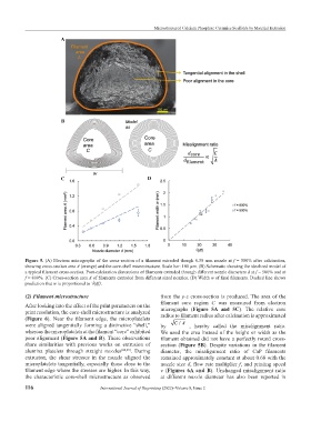
Figure 5. (A) Electron micrographs of the cross-section of a filament extruded though 0.58 mm nozzle at f = 500% after calcination,
showing cross-section area A (orange) and the core-shell microstructure. Scale bar: 100 µm. (B) Schematic showing the idealized model of
a typical filament cross-section. Post-calcination dimensions of filaments extruded through different nozzle diameters d at f = 500% and at
f = 800%. (C) Cross-section area A of filaments extruded from different sized nozzles. (D) Width w of final filaments. Dashed line shows
prediction that w is proportional to √(df).
(2) Filament microstructure from the y-z cross-section is produced. The area of the
filament core region C was measured from electron
After looking into the effect of the print parameters on the micrographs (Figure 5A and 5C). The relative core
print resolution, the core-shell microstructure is analyzed radius to filament radius after calcination is approximated
(Figure 6). Near the filament edge, the microplatelets
/
were aligned tangentially forming a distinctive “shell,” by CA , hereby called the misalignment ratio.
whereas the microplatelets at the filament “core” exhibited We used the area instead of the height or width as the
poor alignment (Figure 5A and B). These observations filament obtained did not have a perfectly round cross-
share similarities with previous works on extrusion of section (Figure 5B). Despite variations in the filament
alumina platelets through straight nozzles [24,25] . During diameter, the misalignment ratio of CaP filaments
extrusion, the shear stresses in the nozzle aligned the remained approximately constant at about 0.68 with the
microplatelets tangentially, especially those close to the nozzle size d, flow rate multiplier f, and printing speed
filament edge where the stresses are higher. In this way, v (Figures 6A and B). Unchanged misalignment ratio
the characteristic core-shell microstructure as observed at different nozzle diameter has also been reported in
116 International Journal of Bioprinting (2022)–Volume 8, Issue 2