
Page 123 - IJB-8-2
P. 123
Dee, et al.
A
B
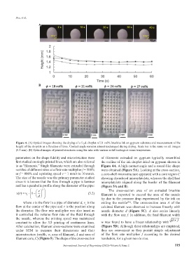
Figure 4. (A) Optical images showing the drying of a 5 µL droplet of 21 vol% brushite ink on gypsum substrate and measurement of the
height of the droplets as a function of time. Contact angle remains almost unchanged during drying. Scale bar is the same on all images
(0.5 mm). (B) Optical images of printed structures using the inks with various solid loadings at room temperature.
parameters on the shape fidelity and microstructure were of filaments extruded on gypsum typically resembled
first studied on single printed lines, which are also referred the outline of the ink droplet dried on gypsum shown in
to as “filaments.” Single filaments were extruded through Figure 4A. A high contact angle and a round-like shape
nozzles of different sizes at a flow rate multiplier f = 500% were obtained (Figure 5A). Looking at the cross-section,
or f = 800% and a printing speed v = 1 mm/s to 10 mm/s. a core-shell microstructure appeared with a core region C
The size of the nozzle was the primary parameter studied showing disordered microplatelets, whereas the shell had
since it is known that the flow through a pipe is laminar microplatelets aligned along the border of the filament
and has a parabolic profile along the diameter of the pipe: (Figure 5A and B).
2 The cross-section area of an extruded brushite
r
v ( ) r = v ⋅ c 1− (3.2) filament is expected to exceed the area of the nozzle
d
tip due to the pressure drop experienced by the ink on
where v is the flow in a pipe of diameter d, v is the exiting the nozzle . The cross-section area A of the
[36]
c
flow at the center of the pipe and r is the position along calcined filament was observed to increase linearly with
the diameter. The flow rate multiplier was also tuned as nozzle diameter d (Figure 5C). A also scales linearly
it controlled the volume flow rate of the fluid through with the flow rate f. In addition, the final filament width
the nozzle, whereas the printing speed was maintained d × f
constant to allow for 3D printing of continuous lines. w was found to have a linear relationship with
After calcination, filament cross-sections were examined (Figure 5D). Although these relationships are empirical,
under SEM to measure their dimensions and their they are convenient as they permit simple adjustment
microstructure (width, w, area of filament, A and area of of the flow rate multiplier f according to the desired
filament core, C) (Figure 5). The shape of the cross-section resolution, for a given nozzle size.
International Journal of Bioprinting (2022)–Volume 8, Issue 2 115