
Page 125 - IJB-8-2
P. 125
Dee, et al.
A B C
D E F
/
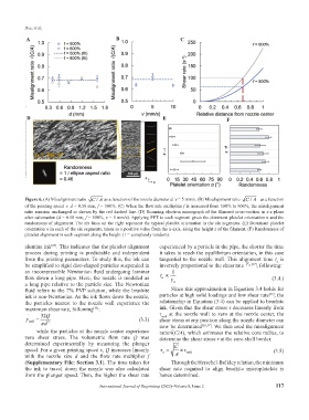
Figure 6. (A) Misalignment ratio CA as a function of the nozzle diameter d. v = 5 mm/s. (B) Misalignment ratio CA as a function
/
of the printing speed v. d = 0.58 mm, f = 500%. (C) When the flow rate multiplier f is increased from 500% to 800%, the misalignment
ratio remains unchanged as shown by the red dashed line. (D) Scanning electron micrograph of the filament cross-section in x-z plane
after calcination (d = 0.58 mm, f = 500%, v = 5 mm/s). Applying FFT to each segment gives the dominant platelet orientation α and the
randomness of alignment. The six lines on the right represent the typical platelet orientation in the six segments. (E) Dominant platelet
orientation α in each of the six segments, taken as a positive value from the x-axis, along the height z of the filament. (F) Randomness of
platelet alignment in each segment along the height (1 = completely random).
alumina ink . This indicates that the platelet alignment experienced by a particle in the pipe, the shorter the time
[27]
process during printing is predictable and independent it takes to reach the equilibrium orientation, in this case
from the printing parameters. To study this, the ink can tangential to the nozzle wall. This alignment time t is
a
be simplified to rigid disc-shaped particles suspended in inversely proportional to the shear rate γ a [37] , following:
an incompressible Newtonian fluid undergoing laminar 1
flow down a long pipe. Here, the nozzle is modeled as t ∝ (3.4.)
a
γ
a long pipe relative to the particle size. The Newtonian a
fluid refers to the 7% PVP solution, while the brushite Since this approximation in Equation 3.4 holds for
[37]
ink is non-Newtonian. As the ink flows down the nozzle, particles at high solid loadings and low shear rate , the
the particles nearest to the nozzle wall experience the relationship in Equation (3.4) can be applied to brushite
maximum shear rate, following : ink. Given that the shear stress τ decreases linearly from
[33]
32Q τ wall at the nozzle wall to zero at the nozzle center, the
γ wall = π d 3 (3.3) shear stress at any position along the nozzle diameter can
while the particles at the nozzle center experience now be determined [28,37] . We then used the misalignment
ratio√(C/A), which estimates the relative core radius, to
zero shear stress. The volumetric flow rate Q was determine the shear stress τ at the core-shell border.
determined experimentally by measuring the plunger C
speed. For a given printing speed v, Q increases linearly τ a = ×τ wall (3.5)
with the nozzle size d and the flow rate multiplier f A
(Supplementary File: Section 3.1). The time taken for Through the Herschel-Bulkley relation, the minimum
the ink to travel down the nozzle was also calculated shear rate required to align brushite microplatelets is
from the plunger speed. Then, the higher the shear rate hence determined.
International Journal of Bioprinting (2022)–Volume 8, Issue 2 117