
Page 185 - IJB-8-2
P. 185
Liu, et al.
A B C
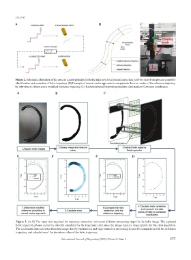
Figure 2. Schematic illustration of the process control principle for helix trajectory detection and correction. (A) Five steps from process control to
identification and correction of helix trajectory. (B) Example of normal vector approach to compensate the error vector of the reference trajectory
by mirroring to obtain a new modified reference trajectory. (C) Extrusion-based bioprinting machine with standard Cartesian coordinates.
A B C
G F E D
Figure 3. (A-G) The input data required for trajectory correction and seven different processing steps for the helix image. The captured
helix trajectory photos cannot be directly calculated by the trajectory error since the image data are unacceptable for the error algorithm.
The coordinate data converted from the image data by binarization and edge extraction processing is used for comparison with the reference
trajectory, and calculation of the deviation value of the helix trajectory.
International Journal of Bioprinting (2022)–Volume 8, Issue 2 177