
Page 184 - IJB-8-2
P. 184
Error Correction for Bioprinting
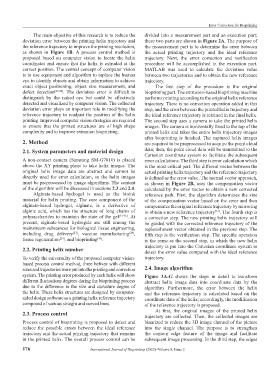
The main objective of this research is to reduce the divided into a measurement part and an execution part;
deviation error between the printing helix trajectory and these two parts are shown in Figure 2A. The purpose of
the reference trajectory to improve the printing resolution, the measurement part is to determine the error between
as shown in Figure 1B. A process control method is the actual printing trajectory and the ideal reference
proposed based on computer vision to locate the helix trajectory. Next, the error correction and verification
coordinates and ensure that the helix is extruded at the procedure will be accomplished in the execution part.
correct position. The central concept of computer vision MATLAB was used to calculate the deviation value
is to use equipment and algorithm to replace the human between two trajectories and to obtain the new reference
eye to identify objects and obtain information to achieve trajectory.
exact object positioning, object size measurement, and The first step of the procedure is the original
defect detection [20-22] . The deviation error is difficult to bioprinting part. The extrusion-based bioprinting machine
distinguish by the naked eye but could be effectively performs printing according to the original helix reference
detected and visualized by computer vision. The collected trajectory. There is no correction operation added in this
deviation error plays an important role in modifying the step, and the error between the printed helix trajectory and
reference trajectory to readjust the position of the helix the ideal reference trajectory is retained in the final helix.
printing. Improved computer vision strategies are required The second step uses a camera to take the printed helix
to ensure that the printed structures are of high shape images. The camera is horizontally fixed to the top of the
complexity and to improve extrusion bioprinting. printed helix and takes the entire helix trajectory images
after bioprinting is finished. The captured helix images
2. Method are required to be preprocessed to acquire the point cloud
2.1. System parameters and material design data; then, the point cloud data will be transmitted to the
Cartesian coordinate system to facilitate the subsequent
A non-contact camera (Samsung SM-G7810) is placed error calculations. The third step is error calculation which
above the XY printing plane to take helix images. The is the most critical part. The different vector between the
original helix image data are abstract and cannot be actual printing helix trajectory and the reference trajectory
directly used for error calculation, so the helix images is defined as the error value. The normal vector approach,
must be preprocessed by image algorithms. The content as shown in Figure 2B, uses the compensation vector
of the algorithm will be discussed in sections 2.3 and 2.4. calculated by the error vector to obtain a new corrected
Alginate-based hydrogel is used as the bioink reference path. First, the algorithm determines the size
material for helix printing. The core component of the of the compensation vector based on the error and then
alginate-based hydrogel, alginate, is a derivative of compensates the original reference trajectory by mirroring
alginic acid, which has the structure of long chains of to obtain a new reference trajectory . The fourth step is
[31]
polysaccharides to maintain the state of the gel [23-26] . At a correction step. The new printing helix trajectory will
present, alginate-based hydrogels are still among the be guided with the corrected reference trajectory of the
mainstream substances for biological tissue engineering, replenishment vector obtained in the previous step. The
including drug delivery , vaccine manufacturing , fifth step is the verification step. The specific operation
[27]
[28]
tissue regeneration , and bioprinting . is the same as the second step, in which the new helix
[29]
[30]
trajectory is put into the Cartesian coordinate system to
2.2. Printing helix number detect the error value compared with the ideal reference
To verify the universality of the proposed computer vision- trajectory.
based process control method, three helixes with different
sizes and trajectories were put into the printing and correction 2.4. Image algorithm
system. The printing error produced by each helix will show Figure 3A-G shows the steps in detail to transform
different fluctuations degrees during the bioprinting process abstract helix image data into coordinate data by the
due to the difference in the size and curvature degree of algorithm. Furthermore, the error between the helix
the helix. These helix structures are designed by computer- and the reference trajectory is calculated based on the
aided design software as a printing helix reference trajectory coordinate data of the helix; accordingly, the modification
composed of various straight and curved lines. of the reference trajectory is proposed.
At first, the original images of the printed helix
2.3. Process control trajectory are collected. Then, the collected images are
Process control of bioprinting is proposed to detect and binarized to reduce the 3D image channel of the picture
reduce the possible errors between the ideal reference into the single channel. The purpose is to strengthen
trajectory and the actual printing trajectory that remains the contour edge feature of the image and facilitate
in the printed helix. The overall process control can be subsequent image processing. In the third step, the edges
176 International Journal of Bioprinting (2022)–Volume 8, Issue 2