
Page 187 - IJB-8-2
P. 187
Liu, et al.
A B C
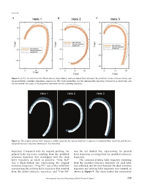
Figure 5. (A-C) The observed solid flesh-colored, black-dashed, and red-dashed lines indicated the print helix locus, reference locus, and
the printed helix centerline estimation, respectively. The black-dashed line was the printing helix trajectory obtained in an ideal state, and
the red-dashed line output of the algorithm represents the helix printing trajectory.
Figure 6. The original printed helix trajectory (white material), the new printed helix trajectory (translucent blue material), and the pre-
designed reference trajectory (translucent blue material).
trajectory. Compared with the original printing, the was the red dashed line representing the printed
printed helix trajectory resulting from the modified helix trajectory resulting from the modified reference
reference trajectory was overlapped with the ideal trajectory.
helix trajectory as much as possible. “Orig Ref” The corrected printing helix trajectory stemming
was a black-dashed line representing the original from the modified reference trajectory for each helix
reference trajectory; “Orig Prt” was a blue solid line was collected, and the error between the ideal reference
representing the printing helix trajectory that resulted trajectory and printing helix trajectory was counted, as
from the initial reference trajectory; and “Corr Prt” shown in Figure 9. The black-dashed line represented
International Journal of Bioprinting (2022)–Volume 8, Issue 2 179