
Page 60 - IJB-8-2
P. 60
CFD Assessment of Extrusion Bioprinting Parameters
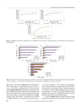
A B
C
Figure 7. Variation of maximum wall shear stress of different nozzle diameters at different pressures. (A) Tapered conical. (B) Conical.
(C) Cylindrical.
A B
C
Figure 8. Graph of maximum wall shear stress at varying inlet pressure for bioinks with different power-law constant using (A) tapered
conical nozzle (D = 0.3 mm), (B) conical nozzle (D = 0.3 mm), and (C) cylindrical nozzle (D = 0.3 mm).
out out out
interval of 2 s are shown in Figure 10. The thread profiles be the same regardless of the chosen nozzle geometry
for the other nozzles at varied printing speeds (1 mms , 5 for a constant diameter at a constant inlet mass flow rate.
−1
mms , and 10 mms ) at the same time intervals are shown A change in the strand width results in decreased accuracy
−1
−1
in the Appendix Figures 1-9. Quantitative assessment of the of the printed strand at higher printing speed as observed
thread profile using volume fraction of the bioink across all experimentally . As such, using CFD to simulate the effect
[22]
three nozzles shows that at lower printing speed, the strand of printing speed can assist in identifying the ideal printing
of extruded bioink is continuous and uniform, but at higher speed for a given bioink in a particular system.
printing speeds, the strand is discontinuous and smaller As shown in Figure 11A, in general, the conical nozzle
in width. Furthermore, the ideal printing speed seems to has the lowest outlet velocity, whereas the cylindrical nozzle
52 International Journal of Bioprinting (2022)–Volume 8, Issue 2