
Page 55 - IJB-8-2
P. 55
Chand, et al.
Academic License for the CFD simulations. Meshes were Where, η is the viscosity (Pa s), n is the power-
generated in Fluent for each nozzle using a hex dominant law constant (unitless), γ is the shear strain rate (s ),
−1
method with default element size (1.4 mm). In hindsight, and K is the flow consistency index (Pa s). The initial
sweep mesh method could have been used. All meshes viscosity of the bioink is given by K and is related to the
had average element quality >0.50 and orthogonal quality extrudability of bioinks, with lower values indicating
>0.60. For the transient simulation, adaptive mesh sizing higher extrudability . Based on the flow behavior
[13]
with a resolution of 6 was used for the nozzle, and sizing index, n: if 0 < n <1, then, the fluid shows pseudo-plastic
of 0.1 mm was used for the bottom environment half of or shear-thinning behavior, with a smaller value of n
the mesh. meaning a greater degree of shear-thinning. If n = 1, the
fluid shows Newtonian behavior, and if n > 1, the fluid
2.2. Bioinks shows dilatant or shear-thickening behavior with a higher
[14]
Four different bioinks whose viscous behavior was value of n resulting in greater thickening .
described by the power-law viscosity model for non- Several studies have previously used the shear-
Newtonian fluids (Equation 1) were chosen from existing dependent power-law to simulate the flow of non-
literature, and the power-law parameters along with the Newtonian bioinks in different nozzle geometries
density are tabulated in Table 2. using empirically obtained K and n values from
curve approximation [2,8,15-17] . In addition, Markstedt
η=K.γ n−1 (1) et al. [18] used a linear PTT model in IPS IBOFlow,
whereas Emmermacher et al. used a model based on
[9]
A B C Herschel-Bulkley law to simulate the fluid flow inside
the nozzle. The Herschel-Bulkley and Carreau-Yasuda
model were considered but the value for required
parameters was not readily available for chosen bioink,
whereas n and K values were more readily available
in the literature. All the chosen bioinks exhibit shear
thinning, that is, viscosity decreases when shear rate
increases. Shear-thinning is a desirable property in
bioinks as it is crucial in determining printability by
preventing clogging of nozzle and reducing shear
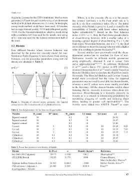
Figure 1. Diagram of selected nozzle geometry. (A) Tapered stress, leading to greater cell survivability [19] . The
®
conical nozzle. (B) Conical nozzle. (C) Cylindrical nozzle. bioinks were added into ANSYS Fluent as user-
Table 1. Nozzle parameters for the three nozzle geometries
Nozzles D (mm) D'' (mm) D (mm) L1 (mm) L2 (mm) α1 α2
out
in
Tapered conical 10 0.1 10 26.84
Tapered conical 10 0.3 10 25.87
Tapered conical 10 0.5 10 25.41
Conical 10 3 0.1 10 10 19.29 8.25
Conical 10 3 0.3 10 10 19.29 7.69
Conical 10 3 0.5 10 10 19.29 7.13
Cylindrical 10 0.1 0.1 10 10 26.34
Cylindrical 10 0.3 0.3 10 10 25.87
Cylindrical 10 0.5 0.5 10 10 25.41
Table 2. Power law parameters and density of bioinks
Bioink K (Pa.s) n Density (kg/m ) Reference
3
Ink 6040 (NFC/alginate) 109.73 0.154 998.2 Dharmadasa [16]
CELLINK Bioink 102.53 0.170 1000 Gómez-Blanco,
Mancha-Sánchez, Marcos [8]
Alginate-Sulfate Nanocellulose 56.503 0.0863 ~1000 Müller, Öztürk, Arlov [17]
CM-cellulose + Alginate + 24.943 0.505 1039.8 Pössl [20]
κ-carrageenan + Gelatin
International Journal of Bioprinting (2022)–Volume 8, Issue 2 47