
Page 50 - IJB-8-3
P. 50
Additive Manufacturing of Bone Scaffolds
elastic regime has been investigated experimentally and the paper, the details related to the various aspects will be
numerically. Moreover, experimental compression tests provided accordingly.
have been conducted to study other effects, including
cell type, printing direction, and material variation. In 2.1. Geometrical design of scaffolds
addition, since the FDM AM technology process results Multi-morphology structures made from TPMS have
in printing anomalies and imperfections, a µCT analysis been widely used in biomechanical scaffolds [37,52,53] . Their
has been used to evaluate the printing quality and to geometries have different functions since the lattice
obtain the real geometry of printed scaffolds. Moreover, structure change in terms of porosity, cellular topology,
the effect of printing direction, cell type, and filament and the material itself [54,55] . As described in the previous
variation has been investigated. A crucial challenge in sections, bone tissue structures vary locally. A typical
the field of biomechanics is the difficulty in conducting knee joint is illustrated in Figure 2. To properly mimic
different mechanical tests. To be more specific, seldom the real geometry of natural bone and cartilage tissues in
a multi-morphology specimen can be designed with an the knee joint, scaffolds made of regions with different
appropriate fixture for experimental tests. To quantify structures, each one suitable for hosting the tissues that
the mechanical response of printed bone scaffolds under are created during healing, must be defined.
different loadings, a method based on the combination of In this work, TPMS structures have been defined
µCT and FEM has been used in this study. using unit cell design based on mathematical equations .
[56]
2. Methods and fabrication These structures are designed so that they have the
minimum surface, that is, the mean curvature is locally
Different steps have been considered to tackle the zero. Each one of these surfaces has a specific equation
problem of obtaining multi-morphology scaffolds with in 3D space. Figure 3 shows three common TPMS
controlled characteristics. The flowchart adopted in the structures whose mathematical definition is provided by
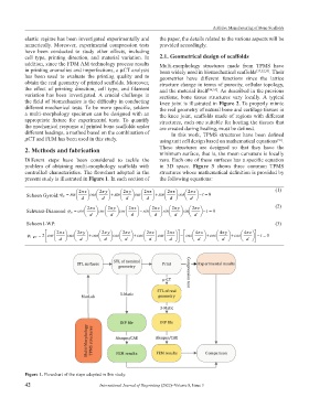
present study is illustrated in Figure 1. In each section of the following equations:
Schoen Gyroid: ϕ = sin 2 xπ cos 2 yπ + sin 2 yπ cos 2 zπ + sin 2 zπ cos 2 xπ t −= 0 (1)
G
d d d d d d
2 xπ 2 yπ 2 zπ 2 xπ 2 yπ 2 zπ (2)
Schwarz-Diamond:ϕ = cos cos cos − sin sin sin t −= 0
D
d d d d d d
Schoen I-WP: (3)
2 π 2 x π 2y π 2 y π 2z π 2 x π 4 z π 4x π 4y π z
ϕ = 2 cos cos + cos cos + cos cos − cos + cos + cos t − = 0
I WP−
d d d d d d d d d
Figure 1. Flowchart of the steps adopted in this study.
42 International Journal of Bioprinting (2022)–Volume 8, Issue 3