
Page 51 - IJB-8-3
P. 51
Noroozi, et al.:
TPMS structures, respectively. Furthermore, γ is the
transitional function defining the structure transition from
φ to φ ; its expression is as follows:
G D
1
γ =
+
1 e Kx (8)
According to the value of the constant K≥0, the
multi-morphology scaffold can change its structure
either suddenly or gradually; the influence of its value
on the resulting TPMS has been studied in this work.
Moreover, since the function (8) depends only on the
spatial coordinate x, the function φ MML defines a structure
that changes from φ to φ along the x coordinate. Further
G
D
Figure 2. Scheme of different tissues present in a knee joint: variation in lattice type can be achieved by relating this
Different bone morphology zones: 1-4. function to the other coordinates.
2.2. 3D printing of TPMS scaffolds
The dimension of the TPMS structure domain, created
using MATLAB software, is 40×20×20 mm . The
3
®
cellular type has been assumed to vary along the axis that
represents the longest edge of the domain. After creating
the mesh with the proper size, the obtained geometry has
been exported in Standard Tessellation Language (STL)
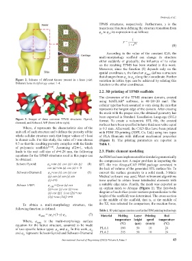
Figure 3. Images of three common TPMS structures: Gyroid, format. To create a volumetric STL file, the created
diamond, and Schoen I-WP (from left to right). surfaces have been specified to have thickness value equal
Where, d represents the characteristic size of the to 0.5 mm. Afterward, the CAD files have been printed
unit cell of each structure and t defines the porosity of the with FDM 3D printing (3DPL Co. Ltd.) using two types
whole cellular structure such that larger values of t lead of PLA filaments with different mechanical properties
to denser cells. For this study, the value of t was chosen (Figure 1). The printing parameters are reported in
0.3 so that the resulting porosity complies with the limits Table 1.
of polymeric scaffolds [57,58] . Assuming d/2=1, which
leads to the unit cell size of d=6.28 mm, the following 2.3. Finite element modeling
equations for the TPMS structures used in this paper can An FEM has been implemented for simulating numerically
be obtained: the compression test. A major problem in importing the
Schoen Gyroid: φ =sin (x) cos (y)+sin (y) (4) STL file into Abaqus/CAE FEM package consisted in
G
cos (z)+sin (z) cos (x)–t=0 the lack of volume of the generated STL surface file. To
Schwarz-Diamond: φ =cos (x) cos (y) cos (5) convert the surface geometry to a solid mesh, 3-Matic
D
(z)–sin (x) sin (y) sin Medical software was used. Mesh refinement algorithms
(z)–t=0 were applied to obtain linear tetrahedral elements with
Schoen I-WP: φ I–WP =2[cos (x) cos (6) a suitable edge ratio. Finally, the mesh was exported as
(y)+cos (y) cos (z)+cos an orphan mesh to Abaqus (Figure 1). The free-body
(x) cos (z)]–[cos (2x)+cos diagram of each slice (cross-sections perpendicular to the
(2y)+cos (2z)]–t=0 height of the scaffold) was determined. The cross-section
at the middle of the scaffold, that is, at the middle of
To obtain a multi-morphology structure, the the TZ, was selected for comparison; the reaction force,
following function is defined:
Table 1. 3D printing parameters used in the FDM printing technology
φ = γφ +(1–γ) φ (7)
MML G D Material Melting Layer Printing Bed
Where, φ MML is the multi-morphology surface temperature height speed temperature
equation for the lattice structure, assumed to be made (°C) (µm) (mm/s) (°C)
of two specific lattice types: φ and φ . In this work, φ PLA 1 190 50 10 24
G
D
G
and φ represent Schoen-Gyroid and Schwarz-Diamond PLA 2 215 50 10 24
D
International Journal of Bioprinting (2022)–Volume 8, Issue 3 43