
Page 55 - IJB-8-3
P. 55
Noroozi, et al.:
exists. Because of the graded structure of natural bone with the same material but different printing direction.
tissues, the effect of the degree of variation between Delamination of the deposited layers is the main reason
two structures (gyroid and diamond) in terms of the of failure in S4H which has been printed horizontally. On
mechanical response has been analyzed in the present the other hand, the weak bonding between layers has not
study. Figure 9B shows the response of a scaffold affected the behavior of vertically printed sample (S12V).
with different K values. According to the value of the Similarly, this mechanism is the governing rule for the
transitional parameter K, the transitional zone varies small strains so that the vertically printed scaffolds will
from a sudden change (K = 20) to a gradual (K = 0.1) have stiffer structure. This justification is true only for
change between the two pure structures present at the two geometry 4 which is a bending-dominated structure.
extremities of the scaffold; specimen S4H has the sharpest However, for the stretching-dominated geometry, the
transition zone, while specimen S7H has the most gradual printing direction does not show a meaningful trend;
transition between gyroid and diamond structures. the comparison between S3H and S11V does not prove
It is worth noticing that an increase in the size of TZ, clearly the hypothesis that vertical printing produces
that is, making the transition in the scaffold more gradual, stiffer scaffolds.
leads to a less stiff scaffold. This behavior stems from To investigate the effect of the filament materials,
the lower porosity of the gyroid structure. According to two different filaments were used for printing the samples.
Figures 7 and 8, by increasing the TZ’s size, the fraction The first reason for using different materials to choose
of gyroid cells is greater than that of diamond ones. As a the best possible materials for biodegradable scaffold
result, the reduction of stiffness stems from this issue, so is achieving different stiffnesses. This mechanical
the porosity of the scaffolds for multi-morphology structure characteristic is crucial when designing a biodegradable
has more importance than the size of transitional zone. scaffold. Due to stress shielding effect, a stiffer material
AM process parameters affect the structural integrity is not always the best option even though its structural
of the printed components because of the local transient integrity would be enhanced. While CNT-PLA material
heat sources that lead to a heterogeneous material. FDM has a different mechanical response than PLA1, it is
is not an exception to this general rule. To see the effects partially conductive; the electrical conductivity, which is
of this variation, geometries 3 and 4 in Table 2 were the result of additional CNT, gives electrical functionality
printed using the same filament under the same curing to the designed scaffolds and expands the applicability of
process. The results of the compression test on these scaffolds printed using this composite filament. Hence,
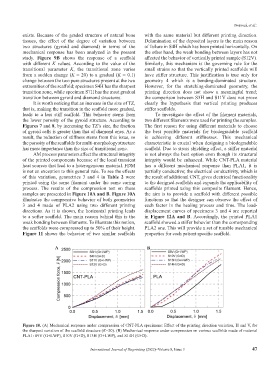
samples are presented in Figure 10A and B. Figure 10A the aim is to provide a scaffold with different possible
illustrates the compressive behavior of both geometries functions so that the designer can observe the effect of
3 and 4 made of PLA2 using two different printing each factor in the healing process and time. The load-
directions. As it is shown, the horizontal printing leads displacement curves of specimens 3 and 4 are reported
to a softer scaffold. The main reason behind this is the in Figure 12A and B. Accordingly, the printed PLA1
weak bonding between filaments. To illustrate this notion, scaffold showed a stiffer behavior than the corresponding
the scaffolds were compressed up to 50% of their height. PLA2 one. This will provide a set of tunable mechanical
Figure 11 shows the behavior of two similar scaffolds properties for each patient specific scaffold.
A B
Figure 10. (A) Mechanical response under compression of CNT-PLA specimens: Effect of the printing direction variation, H and V, for
the sharpest variation of the scaffold structure (K=20). (B) Mechanical response under compression on various scaffolds made of material
PLA1: S9V (G+I-WP), S10V (G+D), S13H (G+I-WP), and S14H (G+D).
International Journal of Bioprinting (2022)–Volume 8, Issue 3 47