
Page 58 - IJB-8-3
P. 58
Additive Manufacturing of Bone Scaffolds
A B
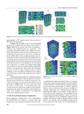
Figure 16. Von Mises stress contours obtained by FEM for specimen S3H by considering its real (A) and nominal (B) geometry.
approximately 12.79% improvement in the accuracy of
the FEM when using µCT.
In Figure 16, the FEM results of real and nominal
geometry of scaffold S3H are shown. Red arrows in
Figure 16B indicate regions with stress concentration.
Therefore, the indicated points are susceptible to fail
more likely than other points of the scaffold. However,
in the real geometry, there are some useful points to be
considered; the gyroid section has stress concentration
in the middle while in the nominal geometry, only the
sharp edges at the boundaries and at the transitional zone
have shown stress concentration. Therefore, each contour
predicts that the material starts failing either in the middle
of the gyroid section or at its boundaries and transitional
zone, respectively. In reality, the designed sharp edges
and geometries cannot be accurately printed using FDM
method. Consequently, the sharp edges and boundaries
do not exist with the edge resolution found in nominal
scaffolds, so the real geometry which has been acquired
using µCT leads to more valid results than the nominal
geometries.
Another point regarding the stress distribution taking Figure 17. Von Mises stress contours for a complex loading on
place in the real geometry is that the additional materials specimen S3H.
that have been melted in the closed-cell structures in the a scaffold should mimic this natural feature for reaching
I-WP section have not experienced any stresses due to
compression (Figure 16A, top right). This means that better results. Approaching that goal is not feasible unless
the variation in the results is not stemmed from those a detailed model is prepared from the multi-morphology
area between knee and cartilage. In addition, applying
printing anomalies. Indeed, the variation of the materials loads on bone scaffolds are not always as simple as a
deposition in the sharp edges and also in the load-bearing uniaxial compression test. Different loads in different
walls of the scaffold is responsible for the difference directions may apply to the scaffold. In this regard, a
between the nominal and µCT results. real-world eccentric loading has been simulated on the
3.3. Real-world biomechanical application real geometry of specimen number 3 (Table 2) to provide
a better prediction of the mechanical behavior of the
Multi-morphology scaffolds have diverse applicability scaffold. This kind of loading is always possible for knee
in biomechanics. For instance, in regions where the joints . For example, when something is being picked
[60]
morphology of the hosting bone changes in the knee joint, up, the direction of the bones are no longer parallel to
50 International Journal of Bioprinting (2022)–Volume 8, Issue 3