
Page 139 - IJB-8-4
P. 139
Cardoza, et al.
The material used to build 3D behavioral arenas is 2.1. PVA casting polyvinyl alcohol; PVOH)
NGM, which is an agar-based hydrogel used to culture
C. elegans in the laboratory. NGM 2% in agar was PVA ([CH2CH(OH)]n) is known for its remarkable
prepared according to standard methods [6,56] . Once all property to dissolve in water, because of its high
the ingredients are diluted in water, NGM is in liquid sensitivity to moisture. This makes it particularly useful
form in temperatures higher than ~45°C (melting point), in 3D printing, when the part at hand needs to have
and it solidifies as it cools down. In room temperature, support when printed, that is, in the case of overhung
polymerized NGM is in solid state. This is a key property structures, which later must be removed, leaving the
for both the PVA casting and Parnon 3D-printing methods. 3D-printed part intact [57,58] . This property, combined
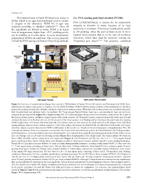
Figure 2. Overview of customization changes that convert a FDM printer to Parnon Printer (left panel), and Parnon-printed NGM three-
dimensional structures (right panel). Left panel: (A) The FDM 3D Printer DOBOT MOOZ (image courtesy of the manufacturer). The three
main parts are the print head, the substrate, and the tri-axial relative motion system. While the stock motion system was considered adequate,
both the print head and substrate had to be modified. (B) The prototype Parnon Printer, featuring a customized print head and substrate,
designed for printing NGM. Figure S1 in Supplementary File. (C) Customized print head, front view schematic, connected to the X-axis of
the triaxial motion system. (i) Bipolar stepper motor of the linear actuator. (ii) 3D-printed custom connector houses the stroke arm (iii) and
connects the motor (i) to the heat sink (v). (iii) Stroke arm of the linear actuator. (iv) Heating element that heats the aluminum sink, keeping
NGM in liquid state. (v) Custom aluminum heat sink. (vi) Custom connector that connects the stroke arm (iii) to the plunger (vii). (vii) Glass
syringe plunger, adhered on the custom connector. (viii) Glass syringe that houses the liquid NGM. (ix) Metal luer-lock nozzle. (x) Copper
wire heat induction system that prevents NGM solidification in the nozzle (ix). Details on the print head parts in Supplementary File. (D)
Customized substrate, front view schematic, connected to the Y-axis of the triaxial motion system. (i) Glass Petri dish. (ii) Plotting medium.
(iii) Peltier device, red arrows indicate direction of heat transfer. (iv) Heat sink to promote the thermal gradient created by the Peltier device
(iii). (iv) Springs used as a 4-point bed leveling system (Figure S2 in Supplementary File). Right panel: The Parnon-printed 3D structures
have visibly smoother surface compared to cast-made ones (Figure 1). (A) Perspective and (B) top view of a 7 × 7 mm square-shaped
print, consisting of three layers, 500 µm thick each. Printing conditions: Head speed 10 mm/s, actuation speed 31 µm/s, printing head specs:
Nozzle ID 813 µm, linear actuator NEMA 14. Inset: A clearly distinguishable nematode, crawling on the printed NGM. (C) Top view of a
7 × 7 mm square print, consisting of three layers, 300 µm thick each. Printing conditions: Head speed 10 mm/s, actuation speed 38 µm/s,
printing head specs: Nozzle ID 254 µm, linear actuator NEMA 8. Yellow frame indicates the smoothly deposed NGM line at the corner
of the square (90° angle deposition). (D) Top view of a 20 × 20 mm square print, consisting of three layers, 300 µm thick each. Printing
conditions: Head speed 10 mm/s, actuation speed 8 µm/s, printing head specs: Nozzle ID 254 µm, linear actuator NEMA 8. (E) Perspective
and (F) top view of a C-shaped print, consisting of three layers, 300 µm thick each. Printing conditions: Head speed 10 mm/s, actuation
speed 38 µm/s, printing head specs: Nozzle ID 254 µm, linear actuator NEMA 8. Although C-shaped parts were not used in any experiments,
they are included here to demonstrate the layering details. Yellow bracket indicates the beveled alignment of layers. Parts in right panel (C),
(D), (E), and (F) are printed with a higher resolution print head (combination of nozzle diameter and linear actuator properties), compared
to the part in right panel (A) and (B). Prints from both print heads are shown for comparison. For reference, the squared-shaped prints
shown in Figures 3 and 4 were generated using the higher resolution print head, as well (see specifications in Supplementary File section).
Figure S7 in Supplementary File.
International Journal of Bioprinting (2022)–Volume 8, Issue 4 131