
Page 140 - IJB-8-4
P. 140
3D Arenas for C. elegans Behavior
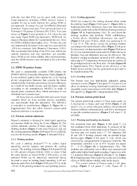
with the fact that PVA can be used with extrusion 2.3.2. Cooling apparatus
fused deposition modeling (FDM) printers, makes it NGM was heated by the heating element when inside
suitable for use as mold material for casting NGM in the printing head (Figure 2 left panel C, Figure S3A in
our approach. To design the cast, SolidWorks (Dassault Supplementary File). Moreover, there was Joule heating
Systemes, France) was used. The cast was printed at an around the nozzle to keep the NGM liquid during extrusion
Ultimaker3 3D printer (Ultimaker BV, USA). The casts (Figure S3 in Supplementary File). To cool down the
shown in Figure 1 were printed in ~5 h. Once the cast plotting medium and facilitate NGM solidification,
was ready, liquid NGM was injected in. NGM took the a Peltier device (Northbear Electronics) was used
[31]
shape of the space that is left vacant inside the cast. Once (Figure 2 left panel D [iii]), which was operating in 16
the NGM solidified thoroughly, after ~30 min, the cast V and 12 A. This device cooled the plotting medium
was immersed in deionized water and was sonicated for according to the thermoelectric effect (Figure 2 left panel
~24 h in a sonicator bath (Branson Ultrasonics, USA). D, red arrows). An aluminum heat sink (Figure 2 left panel
This accelerated dissolving of the PVA cast, which was D [iv]) was implemented underneath the Peltier device to
entirely dissolved and was, therefore, not reusable. dissipate heat and ultimately increase its efficiency. The
Since NGM is not water-soluble after polymerization, Parnon’s cooling mechanism operated at 86% efficiency,
only the NGM structure was left intact at the end of this achieving a 2°C temperature decrease from the surface of
process. the plotting medium to the floor after ~20 min (Figure S6
2.2. FDM 3D printer frame in Supplementary File). Details on the efficiency of the
Peltier device and the heat flux generated are provided in
We used a commercially available FDM printer, the the Supplementary File.
DOBOT MOOZ-2 machine (Shenzhen, China; Figure 3).
It was preferred against other options due to (i) existing 2.3.3. Leveling system
gCode interpretation firmware that controls the linear The Parnon used four individually adjustable spring
actuators in the Cartesian axis system, (ii) price efficiency, resistance screws (Figure 2 left panel D [iv] and [v]) to
as a result of low build volume, and (iii) frame rigidity. allow for substrate leveling. Additional circular levels with
According to the manufacturer, MOOZ-2 is made of adjustable screws were placed on the Petri dish (Figure 2
aircraft grade aluminum alloy, which minimizes in situ left panel D [i], Figure S2 in Supplementary File).
vibrations and increases rigor.
All three axes are controlled with lead screw linear 2.4. Parnon custom print head
actuators which are more accurate, precise, repeatable, The custom print head consists of three major parts: (i)
and user-friendly than the alternative. The MOOZ-2 A mechanism to house and heat NGM (Figure 2 left
is amenable to modifications (Figure 3, Figure S1 in panel C [iv], [v], [vii], [viii], [ix], and [x]), (ii) gCode and
Supplementary File) that allow Parnon’s custom print Arduino software communication, and (iii) a mechanism
head and substrate to be attached. to provide actuation pressure (Figure 2 left panel C [i]
2.3. Parnon custom substrate and [iii]).
Parnon’s substrate is designed to limit liquid spreading 2.4.1. Housing and heating mechanism
and promote build up along the Z-axis (Figure 2). The The aluminum heat sink (Figure 2 left panel C [v])
custom substrate consists of three major parts: (i) The was machined from 6020 aluminum. It connects all the
plotting medium (Figure 2, left panel D [i] and [ii]), (ii) components on the custom print head to Parnon’s X-axis.
the cooling apparatus (Figure 2 left panel D [iii] and [iv]), The heat sink was heated with a 3” 3/8” diameter, 200
and (iii) the leveling system (Figure 2 left panel D [v]). W and 120 V heating element with an internal k-type
thermocouple (Figure 2 left panel C [iv]), which was
2.3.1. Plotting medium
controlled by a programmable temperature controller. The
We used a plotting medium [39,59,60] to reduce liquid temperature controller is set at 65°C because we expect
spreading, provide support, and promote the cooling G’ = ~5 Pa (Figure S6 in Supplementary File). This
process. The plotting medium (Figure 2 left panel D[ii]) modulus was sufficiently low to allow easy extrusion and
is 1.4% glycerin (Sigma-Aldrich, USA) in water. It has sufficiently high to limit liquid spreading. Copper wire with
the same density as liquid NGM (1.024 g/mL), so the 5 V potential difference (Figure 2 left panel C [x], Figure
extruded NGM can be effectively suspended during S3 in Supplementary File) heated the nozzle (joule heating
the print to assist in limiting liquid spreading. A 60 mm effect) so NGM did not solidify while in the nozzle.
diameter glass Petri dish (Figure 2 left panel D [i]) holds The current version of Parnon used a 3 mL glass
~20 mL of the plotting medium for each printing session. syringe (Figure 2 left panel C [viii], Figure S3 in
132 International Journal of Bioprinting (2022)–Volume 8, Issue 4