
Page 233 - IJB-8-4
P. 233
Wang, et al.
A B C
E F
D
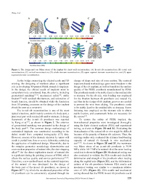
Figure 1. The design and von Mises stress of the implant for chest wall reconstruction. (A) In-suit rib reconstruction; (B) costal arch
reconstruction; (C) vertical reconstruction; (D) whole sternum reconstruction; (E) upper segment sternum reconstruction; and (F) upper
segment sternum reconstruction.
As the bridge connecting the clinical needs and 3D change of shape and size of cross-section. The centroid
printing, the designing of implants plays a significant trajectory-based methodology gave more freedom in the
role in developing 3D-printed PEEK sternal rib implants. design of the rib implant, as well as benefitted the surface
In the design, the clinical needs of implants must be quality of the PEEK prosthesis manufactured by FDM.
comprehensively considered; thus, the criteria, including The prosthesis needs to be stably fixed to the residual ribs
geometrical matching [11,51] , mechanical safety , stable or sternum. On the rib side, wire binding was employed
[36]
fixation with residual ribs/sternum, and restoration of for the fixation between rib prosthesis and natural rib,
[52]
breath function, should be obtained while the limitation and thus in the design of rib implant, grooves are needed
from 3D printing processes on the design of the implant to prevent the wire from sliding. The prosthesis needs
should be seen as a constraint. to be stably fixed to the residual ribs or sternum. Screw
The in-suit rib reconstruction is one of the most fastening was employed on the sternum side to obtain
typical situations, and it mainly consists of a body part, a stable fixation, and countersunk holes are necessary for
junctional part with residual rib and/or sternum. A design the screws .
[14]
framework of the in-suit rib prosthesis was reported To ensure the safety of PEEK implant, the
by Kang et al. , as shown in Figure 2. The criterion biomechanical properties were investigated thoroughly
[37]
of geometrical matching was presented in the design of using the finite element analysis (FEA) and experiment
the body part . The common design methodology of testing, as shown in Figure 2D and 2G. Evaluating the
[53]
customized implants was constructed according to the biomechanics of the natural rib in vivo might be difficult
defect model from computed tomography (CT) data. because of the paucity of human rib cadavers. Thus, the
However, erosion of the thoracic skeleton by tumor will existing studies only evaluated the ultimate load-bearing
result in partial bone loss or severe deformity, restricting capacity of natural rib through in vitro mechanical
the application of traditional design. Meanwhile, due to test [57,58] . As shown in Figure 2E and 2F, the maximum
the complex geometric morphology characteristics and von Mises stress of an in-suit rib prosthesis is 39.88
cross-section properties of natural ribs, the stair-stepping MPa, while 143.7 MPa for natural rib at the same loading
effect for the direct replication model of natural ribs condition is shown in Figure 2D. Mechanical testing was
[54]
is significant during the printing process of FDM, which also conducted to validate the FEA results and check the
affects the surface quality and service performance [55,56] . deformation and strength of the prosthesis when loading
Therefore, a new method based on the centroid trajectory along the sagittal axis (Figure 2G), and the deformation
of the natural rib was developed for the design of pattern of the rib prosthesis between FEA results and
the body part of the in-suit rib prosthesis, as shown in mechanical testing was similar to a maximum relative
Figure 2C , by which the mechanical properties of the error of 20% (Figure 2I). FEA results and mechanical
[37]
rib prosthesis can be conveniently adjusted through the testing showed that the PEEK in-suit rib prosthesis could
International Journal of Bioprinting (2022)–Volume 8, Issue 4 225