
Page 267 - IJB-8-4
P. 267
Xu, et al.
A B
C
D E
F G
H
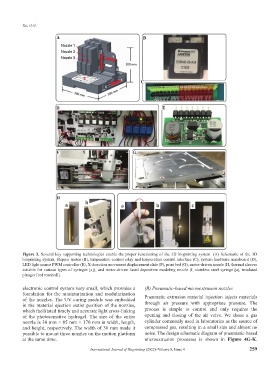
Figure 3. Several key supporting technologies enable the proper functioning of the 3D bioprinting system. (A) Schematic of the 3D
bioprinting system. Stepper motor (B), temperature control relay and temperature control interface (C), system hardware mainboard (D),
LED light source PWM controller (E), X-direction movement displacement slide (F), print bed (G), motor-driven nozzle (H, thermal sleeves
suitable for various types of syringes [a]), and motor-driven fused deposition modeling nozzle (I, stainless steel syringe [a], insulated
plunger [red marked]).
electronic control system very small, which provides a (B) Pneumatic-based microextrusion nozzles
foundation for the miniaturization and modularization
of the nozzles. The UV curing module was embedded Pneumatic extrusion material injection injects materials
in the material ejection outlet position of the nozzles, through air pressure with appropriate pressure. The
which facilitated timely and accurate light cross-linking process is simple to control and only requires the
of the photosensitive hydrogel. The size of the entire opening and closing of the air valve. We chose a gas
nozzle is 30 mm × 85 mm × 170 mm in width, length, cylinder commonly used in laboratories as the source of
and height, respectively. The width of 30 mm made it compressed gas, resulting in a small size and almost no
possible to mount three nozzles on the motion platform noise. The design schematic diagram of pneumatic-based
at the same time. microextrusion processes is shown in Figure 4G-K.
International Journal of Bioprinting (2022)–Volume 8, Issue 4 259