
Page 311 - IJB-9-1
P. 311
International Journal of Bioprinting Error assessment and correction
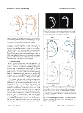
Figure 5. Image overlay of the fabrication helix at different stages to detect
the correction effect for each helix. The white path represents the origi-
nal path, the transparent blue path represents the corrected path, and the
black dotted line represents the as-designed reference path.
Figure 4. The helix and antihelix printing trajectory data points (flesh-
colored solid), the as-designed reference trajectory (black dash line), and
the centerline of the printing trajectory (red dotted line). The centerline
reflects the printing trajectory of the material in the joint space.
computer vision-based image method (Figure 4). The
actual helix printing path deviated from the as-designed
reference path, thus necessitating additional supervision.
The flesh-colored path represents the helix and antihelix
printing path, while the black dashed line represents the
reference path; the red dotted line represents the centerline
of the helix and antihelix path, which reflects the coordinate
position of the printing path and facilitates the calculation
of the deviation value from the reference path.
3.2. Correct printing
Through computer vision-based algorithm processing, the
accuracy of the two helix trajectories improved significantly.
Figure 5 illustrates the helix and antihelix printing path
resulting from the modified reference path and the original
reference path to compare the correction effects. The white
path represents the original helix and antihelix printing
path, the transparent blue path represents the printing path
resulting from the modified reference path, while the black
double-dotted line represents the as-designed reference path.
The original reference path, modified reference path,
original helix and antihelix printing path, as well as the
new helix and antihelix printing path were analyzed and
compared in Figure 6. The topmost figures show the
as-designed original reference path and the modified
reference path with the compensation vector. The black Figure 6. Top: comparison of the modified reference path (blue solid line,
dashed line represents the original reference path, while the Corr Ref), used to fabricate the Corrected Print, with the original refer-
blue solid line represents the modified reference path. The ence path (black dash line, Orig Ref), used to fabricate the Original Print.
bottom figures show the helix and antihelix printing path Bottom: comparison of the original fabrication path (blue solid line, Orig
Prt), resulting from reference path, with the corrected fabrication path
resulting from the modified reference path, which is closer (pink dotted line, Corr Prt).
to the as-designed reference path than the original helix
and antihelix printing path. The blue solid line represents and antihelix printing path resulting from the modified
the helix and antihelix path resulting from the original reference path, and the black dotted line represents the
reference path, the red dotted line represents the helix original reference path.
V
Volume 9 Issue 1 (2023)olume 9 Issue 1 (2023) 303 https://doi.org/10.18063/ijb.v9i1.644