
Page 310 - IJB-9-1
P. 310
International Journal of Bioprinting Error assessment and correction
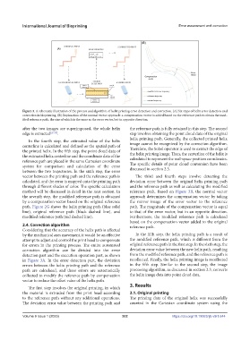
Figure 3. A schematic illustration of the process and algorithm of helix printing error detection and correction. (A) Six steps of helix error detection and
correction in bioprinting. (B) Explanation of the normal vector approach: a compensation vector is added based on the reference path to obtain the mod-
ified reference path, the size of which is the same as the error vector, but in opposite direction.
after the two images are superimposed, the whole helix the reference path is fully retained in this step. The second
edge is extracted [35-37] . step involves obtaining the point cloud data of the original
In the fourth step, the estimated value of the helix helix printing path. Generally, the collected printed helix
centerline is calculated and defined as the spatial path of image cannot be recognized by the correction algorithm.
the printed helix. In the fifth step, the point cloud data of Therefore, the Sobel operator is used to extract the edge of
the estimated helix centerline and the coordinate data of the the helix printing image. Then, the centerline of the helix is
reference path are placed in the same Cartesian coordinate calculated to represent the real-space position coordinates.
system for comparison and calculation of the error The specific details of point cloud conversion have been
between the two trajectories. In the sixth step, the error discussed in section 2.3.
vector between the printing path and the reference path is The third and fourth steps involve detecting the
calculated, and the error is mapped onto the printing path deviation error between the original helix printing path
through different shades of color. The specific calculation and the reference path as well as calculating the modified
method will be discussed in detail in the next section. In reference path. Based on Figure 3B, the normal vector
the seventh step, the modified reference path is obtained approach determines the compensation vector by taking
by a compensation vector based on the original reference the mirror image of the error vector to the reference
path. Figure 2G shows the helix printing path (blue solid path. The magnitude of the compensation vector is equal
line), original reference path (black dashed line), and to that of the error vector, but in an opposite direction.
modified reference path (red dashed line). Furthermore, the modified reference path is calculated
based on the compensation vector added to the original
2.4. Correction algorithm reference path.
Considering that the accuracy of the helix path is affected
by the mechanical axes movement, it would be an effective In the fifth step, the helix printing path is a result of
attempt to adjust and control the print head to compensate the modified reference path, which is different from the
for errors in the printing process. The entire automated original reference path in the first step. In the sixth step, the
correction algorithm can be divided into the error deviation error value between the new helix path, resulting
detection part and the execution operation part, as shown from the modified reference path, and the reference path is
in Figure 3A. In the error detection part, the deviation recollected. Finally, the helix printing image is recollected
errors between the helix printing path and the reference in the fifth step. Similar to the second step, the image
path are calculated, and these errors are automatically processing algorithm, as discussed in section 2.3, converts
collected to modify the reference path by compensation the helix image data into point cloud data.
vector to reduce the offset value of the helix path.
The first step involves the original printing, in which 3. Results
the material is extruded from the print head according 3.1. Original printing
to the reference path without any additional operations. The printing data of the original helix was successfully
The deviation error value between the printing path and counted in the Cartesian coordinate system using the
Volume 9 Issue 1 (2023)olume 9 Issue 1 (2023) 302 https://doi.org/10.18063/ijb.v9i1.644
V