
Page 349 - IJB-9-1
P. 349
International Journal of Bioprinting High-performance electrospun PVDF/AgNP/Mxene fiber
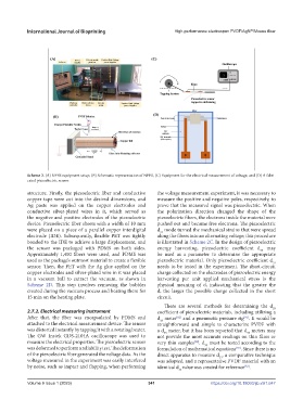
Scheme 2. (A) NFES equipment setup, (B) Schematic representation of NFES, (C) Equipment for the electrical measurement of voltage, and (D) A fabri-
cated piezoelectric sensor.
structure. Firstly, the piezoelectric fiber and conductive the voltage measurement experiment, it was necessary to
copper tape were cut into the desired dimensions, and measure the positive and negative poles, respectively, to
Ag paste was applied on the copper electrodes and prove that the measured signal was piezoelectric. When
conductive silver-plated wires in it, which served as the polarization direction changed the shape of the
the negative and positive electrodes of the piezoelectric piezoelectric fibers, the electrons inside the material were
device. Piezoelectric fiber sheets with a width of 10 mm pushed out and became free electrons. The piezoelectric
were placed on a piece of a parallel copper interdigital d mode turned the mechanical strains that were spread
33
electrode (IDE). Subsequently, flexible PET was tightly along the fibers into an alternating voltage; this procedure
bonded to the IDE to achieve a large displacement, and is illustrated in Scheme 2C. In the design of piezoelectric
the sensor was packaged with PDMS on both sides. energy harvesting, piezoelectric coefficient d may
33
Approximately 1,400 fibers were used, and PDMS was be used as a parameter to determine the appropriate
used as the package’s outmost material to create a flexible piezoelectric material. Only piezoelectric coefficient d 33
sensor. Then, the PET with the Ag glue applied on the needs to be tested in the experiment. The short-circuit
copper electrodes and silver-plated wire in it was placed charge collected on the electrodes of piezoelectric energy
in a vacuum ball to extract the vacuum, as shown in harvesting per unit applied mechanical stress is the
Scheme 2D. This step involves removing the bubbles physical meaning of d, indicating that the greater the
created during the vacuum process and heating them for d, the larger the possible charge collected in the short
15 min on the heating plate. circuit.
There are several methods for determining the d
33
2.7.2. Electrical measuring instrument coefficient of piezoelectric materials, including utilizing a
After that, the fiber was encapsulated by PDMS and d meter and a pneumatic pressure rig . It would be
[91]
[82]
33
attached to the electrical measurement device. The sensor straightforward and simple to characterize PVDF with
was distorted instantly by tapping it with a rotating beater. a d meter, but it has been reported that d meters may
33
33
The GW Instek GDS-2104A oscilloscope was used to not provide the most accurate readings on thin films or
measure the electrical properties. The piezoelectric sensor very thin samples . d must be tested according to the
[92]
33
was deformed to perform a reliability test. The deformation formulation of mathematical equations . Since there is no
[93]
of the piezoelectric fiber generated the voltage data. As the direct apparatus to measure d , a comparative technique
33
voltage measured in the experiment was easily interfered was adopted, and a representative PVDF material with an
by noise, such as impact and flapping, when performing identical d value was created for reference .
[82]
33
V 341 https://doi.org/10.18063/ijb.v9i1.647
Volume 9 Issue 1 (2023)olume 9 Issue 1 (2023)