
Page 348 - IJB-9-1
P. 348
International Journal of Bioprinting High-performance electrospun PVDF/AgNP/Mxene fiber
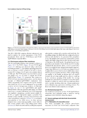
Figure 1. (A) Schematic representation of the synthesis of MXene. Electrospinning solutions of (B) pure PVDF, as well as (C) PVDF/AgNP and (D) PVDF/
AgNP/MXene composites. Digital images of (E) pure PVDF, (F) PVDF/MXene, and (G) PVDF/AgNP/MXene fiber sheets. SEM images of (H) PVDF/
MXene and (I, J) PVDF/MXene/AgNP fibers.
The JEOL JSM-6380 scanning electron microscope was solution into a syringe with a stainless-steel needle tip. The
used to analyze the surface appearance of the PVDF propelling syringe was filled with the configured polymer
piezoelectric fibers and the PVDF/Mxene and PVDF/ solution and attached to the precision flow propulsion
AgNP/MXene composite fibers. pump. The stainless-steel needle was connected to a power
supply with high-voltage electric field (positive electrode)
2.5. Electrospun polymer fiber membrane to function as the NFES nozzle. The grounding end was a
The electrospinning solutions were prepared as shown in glass tube (outer diameter: 20 mm; thickness: 0.50 mm) that
Figure 1B–D. The PVDF (Figure 1B) and PVDF/AgNP contained the piezoelectric fibers, a direct current (DC)
(Figure 1C) solutions were prepared using a previously motor, and a negative high-voltage power supply (negative).
reported procedure [89,90] . The optimal operating parameters Copper tape (thickness: ca. 0.10 mm) was wrapped around
were as follows: a PVDF content of 18 wt%, a direct- the glass tube to ensure that the electric field makes contact
current (DC) voltage of 14 kV, and a tube rotation velocity with the ground (negative electrode). When a high voltage
of 1900 rpm. The PVDF powder was dissolved in acetone was applied to the needle, an electric field was formed
and DMSO (1:1, v/v). In order to prepare the PVDF/ between the spinning needle and the collector, resulting
AgNP/MXene (Figure 1D) composite fiber membrane, in the continuous spinning of the needle. The moving
PVDF (18 %wt) was dissolved in acetone, and the desired platform was controlled by a computer to move the needle
amounts of MXene-AgNP/DMSO suspensions were laterally to collect the orderly and non-small area fibers
added, respectively, under magnetic stirring; the mixtures with a specific stretching direction. Fibrous membranes
were stirred for 12 h at room temperature in an airtight were collected using a grounded, revolving collector. The
container to form homogeneous solutions. As illustrated fibers were dried at room temperature overnight.
in Figure 1C and D, the AgNP/DMSO and AgNP-
MXene/DMSO solutions appeared pale-yellow and black, 2.6. Mechanical properties
respectively. A research laboratory-scale NFES apparatus The mechanical properties of the PVDF/AgNP/MXene
was employed, comprising a positive power supply (0– composites were evaluated using a universal testing
40 kV), a negative high-power supply, a precision flow equipment (AGS-50KNXD, Shimadzu, Japan).
infusion pump, a needle, a rotating collection device, and
a dual-axis platform controller. Scheme 2A is a schematic 2.7. Sensor package and electrical characteristic
representation of the NFES device; its three primary measurement
elements were a metal spinning needle, a metal collector 2.7.1. Fabrication of a wearable sensor
with reverse polarity, and a high-voltage power source This study investigates the complex piezoelectric
(Scheme 2B). NEFS was performed by loading the prepared responses of PVDF and PVDF-based composite fiber
V
Volume 9 Issue 1 (2023)olume 9 Issue 1 (2023) 340 https://doi.org/10.18063/ijb.v9i1.647