
Page 25 - IJB-9-4
P. 25
International Journal of Bioprinting Lattice-Solid hybrid 3D printing for artificial implant
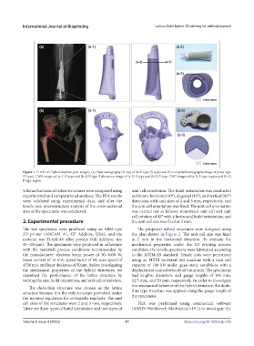
Figure 1. Ti-6AI-4V hybrid implant post-surgery. (a) Plain radiography (X-ray) of shell-type (S-type) and (b) computed tomography image of pizza-type
(P-type). CAD images of (a-1) S-type and (b-1) P-type. Laboratory image of (a-2) S-type and (b-2) P-type. CAD images of (a-3) S-type region and (b-3)
P-type region.
volume fractions of lattice structures were compared using unit cell orientation. The build orientation was conducted
experimental and computational analyses. The FEA results as follows: horizontal (0°), diagonal (45°), and vertical (90°)
were validated using experimental data, and after the directions with unit sizes of 2 and 3 mm, respectively, and
tensile test, microstructure analysis of the cross-sectional the unit cell orientation was fixed. The unit cell orientation
area of the specimens was conducted. was carried out as follows: nonrotated unit cell and unit
cell rotation of 45° with a horizontal build orientation, and
2. Experimental procedure the unit cell size was fixed at 2 mm.
The test specimens were produced using an EBM-type The proposed hybrid structures were designed using
3D printer (ARCAM A1, GE Additive, USA), and the the plan shown in Figure 2. The unit cell size was fixed
material was Ti-6Al-4V alloy powder (GE Additive, size at 2 mm in the horizontal direction. To evaluate the
45–106 µm). The specimens were produced in adherence mechanical properties under the 3D printing process
with the material’s process conditions recommended by condition, the tensile specimens were fabricated according
the manufacturer: electron beam power of 50–3000 W, to the ASTM-E8 standard. Tensile tests were performed
beam current of 15 mA, speed factor of 60, scan speed of using an MTDI universal test machine with a load cell
4530 m/s, and layer thickness of 50 μm. Before investigating capacity of 100 kN under quasi-static conditions with a
the mechanical properties of the hybrid structures, we displacement control velocity of 3 mm/min. The specimens
examined the performance of the lattice structure by had lengths, diameters, and gauge lengths of 140 mm,
varying the size, build orientation, and unit cell orientation. 12.5 mm, and 50 mm, respectively. In order to investigate
The dode-thin structure was chosen as the lattice the mechanical behavior of the hybrid structure, the dode-
structure because it is the only structure permitted under thin type structure was applied along the gauge length of
the national regulation for orthopedic implants. The unit the specimens.
cell sizes of the structures were 2 and 3 mm, respectively. FEA was performed using commercial software
There are three types of build orientation and two types of (ANSYS Workbench Mechanical v19.1) to investigate the
Volume 9 Issue 4 (2023) 17 https://doi.org/10.18063/ijb.716