
Page 30 - IJB-9-4
P. 30
International Journal of Bioprinting Lattice-Solid hybrid 3D printing for artificial implant
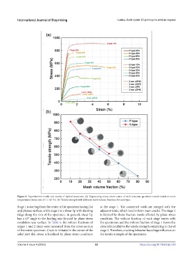
Figure 9. Experimental tensile test results of hybrid structures. (a) Engineering stress–strain curve of each structure specimen tensile-tested at room
temperature (strain rate of 1 × 10 /s). (b) Tensile strength with different mesh volume fractions for each type.
−3
Stage 1 is starting from the center of the specimen having flat at the stage 1. The coarsened voids are merged with the
and plateau surface, while stage 2 is a shear lip with slanting adjacent voids, which lead to form main cracks. The stage 2
ridge along the rim of the specimen. In general, shear lip is formed by shear fracture mode affected by plane stress
has a 45° angle to the loading axis formed by plane stress condition. The volume fraction of each stage varies with
condition near surface. In Table 4, the volume fractions of the specimens, and the volume fraction of stage 1 shows the
stages 1 and 2 areas were measured from the cross-section close relationship to the tensile strength comparing to that of
of the entire specimen. Crack is initiated in the center of the stage 2. Therefore, cracking behavior has a huge influence on
solid part that stress is localized by plane strain condition the tensile strength of the specimens.
Volume 9 Issue 4 (2023) 22 https://doi.org/10.18063/ijb.716