
Page 26 - IJB-9-4
P. 26
International Journal of Bioprinting Lattice-Solid hybrid 3D printing for artificial implant
Figure 2. Schematic of lattice structure specimen. (a) Orientation; (b) unit cell size; (c) unit cell rotation.
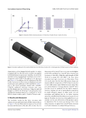
Figure 3. Boundary conditions for FEA results of hybrid structure with volume fraction 10%. (a) Mesh generation. (b) Fixed support and load conditions.
characteristics of the designed hybrid models. To reduce Mises stress of the 3 mm/0° lattice structure was the highest
computational time, the symmetry condition was applied at 1611 MPa, and that of the 2 mm/45° lattice structure was
to the hybrid structure specimens’ centerline, the end of the the lowest at 1456 MPa. While the yield strength of EBM
specimen surface at gauge length was fixed, and a uniform Ti-6Al-4V is about 915–1200 MPa , the three lattice
[31]
compressive load of 500 N was applied to the specimen structures have higher maximum von Mises stress. These
grip (Figure 3). In addition, for the calibration of the FEA FEA results show that the three fully porous designs are
model, maximum von Mises stress and displacements were unsustainable for compression of 500 N, thus it is essential
tested under load conditions of 400 N and 600 N (Tables 1
and 2). For hybrid specimens, meshes with 1,500,000– to have solid-porous mixed hybrid structure rather than
5,700,000 tetrahedral solid-type elements were used, pure porous structure. Consequently, the 2 mm/45° lattice
and the element size was 2.6448 mm. Using the material structure would be preferable for the hybrid structure.
designer in ANSYS, the following Ti alloy properties were However, implants are not as standardized as specimens
3
calculated for the lattice structure: ρ = 0.18 g/cm , Ε = 41.65 in actual orthopedic surgery. In other words, unit cell
MPa for elastic modulus, and ν = 0.486 for Poisson’s ratio. orientation and building axis for the lattice structure
cannot be controlled when the lattice is used as part of a real
3. Results and discussion implant. Therefore, the direction of the applied force is not
The simulation results for the lattice structures with constant, and the unit cell direction of the specimen cannot
various unit sizes and rotated unit cell directions are shown be determined. For the worst-case testing of the 2 mm
in Figure 4. The von Mises stress increases as the unit size lattice structure, we applied the 2 mm/0° lattice structure
increases and decreases as the unit cell is rotated. The von to all hybrid structures to evaluate their performance.
Volume 9 Issue 4 (2023) 18 https://doi.org/10.18063/ijb.716