
Page 39 - IJB-9-6
P. 39
International Journal of Bioprinting Transdermal delivery of printed cisplatin
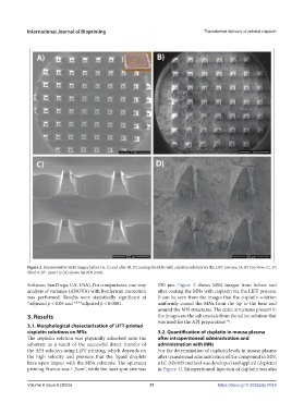
Figure 2. Representative SEM images before (A, C) and after (B, D) coating the MNs with cisplatin solution via the LIFT process. (A, B) Top view; (C, D)
tilted at 20°. Insert in (A) shows the MN patch.
Software, San Diego, CA, USA). For comparisons, one-way 150 µm. Figure 2 shows SEM images from before and
analysis of variance (ANOVA) with Bonferroni correction after coating the MNs with cisplatin via the LIFT process.
was performed. Results were statistically significant at It can be seen from the images that the cisplatin solution
*adjusted p < 0.05 and ****adjusted p < 0.0001. uniformly coated the MNs from the tip to the base and
around the MN structures. The cubic structures present in
3. Results the images are the salt crystals from the saline solution that
was used for the API preparation .
[36]
3.1. Morphological characterization of LIFT-printed
cisplatin solutions on MNs 3.2. Quantification of cisplatin in mouse plasma
The cisplatin solution was physically adsorbed onto the after intraperitoneal administration and
substrate as a result of the successful direct transfer of administration with MNs
the API solution using LIFT printing, which depends on For the determination of cisplatin levels in mouse plasma
the high velocity and pressure that the liquid droplets after transdermal administration of the compound in MN,
have upon impact with the MNs substrate. The optimum a LC-MS/MS method was developed and applied (depicted
printing fluence was 1 J/cm , while the laser spot size was in Figure 3). Intraperitoneal injection of cisplatin was also
2
Volume 9 Issue 6 (2023) 31 https://doi.org/10.36922/ijb.0048