
Page 65 - IJOCTA-15-3
P. 65
FPGA design and implementation of fuzzy learning control: Application on DC motor position control
y m (kt)
RM Fuzzy Inverse Model (FIM)
BIMF 4 g cm
c r (kt)
p (kt) z - 1
KBM g p BOMF 2 IM
z
DF 2
Storage
Learning Mechanism BIMF 3 g em e r (kt)
r (kt) e (kt)
g e BIMF 1
DC Motor
z - 1 IM BOMF 1 DF 1 g u Model y (kt)
z
g c BIMF 1
c (kt) Fuzzy Controller (FC)
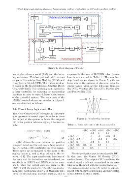
Figure 1. Block diagram of FMRLC
motor, the reference model (RM), and the learn- expressed in the form of IF-THEN rules. Its rule
ing mechanism. This last part is divided into two base is summarized in Table 1. The member-
subparts: Knowledge Base Modifier (KBM) and ship functions are shown in Figure 2, with five
Fuzzy Inverse Model (FIM). This control strategy fuzzy sets on the universe of discourse, with lin-
is based on the Model Reference Adaptive Direct guistic values, which are the following: Negative
Control (MRAC). This method aims to synthesize Big (NB), Negative (N), Zero (ZE), Positive (P),
a fuzzy controller, by adjusting its membership and Positive Big (PB).
functions in order to reject different disturbances
of the controlled system. The main parts of the
NB N ZE P PB
FMRLC control scheme are detailed in Figure 1
and are described as follows:
2.1. Direct fuzzy logic controller
The Fuzzy Controller (FC) designed in this paper -1 1
is to generate a control signal in order to force
the output of the system to follow the assigned Figure 2. Membership functions
DC motor position reference signal; it has two in-
puts: Table 1. Initial rule base of the fuzzy controller
e (kt) = r (kt) − y (kt) (1) c (kt) c (kt) c (kt) c (kt) c (kt)
-1 -0.5 0 0.5 1
z − 1 e (kt) -1 -1 -1 -1 -0.5 0
c (kt) = e (kt) (2)
z e (kt) -0.5 -1 -1 -0.5 0 0.5
e (kt) defines the error between the position e (kt) 0 -1 -0.5 0 0.5 1
reference signal and the position output signal of e (kt) 0.5 -0.5 0 0.5 1 1
the DC motor, c (kt) constitutes the error change. e (kt) 1 0 0.5 1 1 1
These inputs are normalized by the mean of the
scaling factors g e and g c that belong to the in- The defuzzification part is introduced in DF1.
terval [-1 1]. The input membership functions of In this case, the Center Of Gravity (COG)
the error and its derivatives are introduced, re- method is used. The output of FC constitutes the
spectively, in BIMF1 and BIMF2 with the num- control signal u (kt) and normalized to the same
ber 5, while the output ones are given in the interval as the input with the scaling factor g u .
BOMF1 with the number 5. The inference mecha- The dynamic model of the DC motor is approxi-
nism (IM) used in this study is of Mamdani type mated with the first-order model and represented
based on the min-max inference method, and is in the Reference Model (RM).
437