
Page 68 - IJOCTA-15-3
P. 68
M. A. Touat / IJOCTA, Vol.15, No.3, pp.435-448 (2025)
finally implemented on the hardware (FPGA) and by HDL Coder. The encoder output was pro-
then tested on the Simulink environment through grammed as 16 bits, while the PWM input was
the FIL functionality. 21 In this study, the Xilinx programmed as 8 bits. The controller output was
Zedboard is used, which has a Zynq-7000 AP SoC calculated using the Fixed-Point Tool by combin-
XC7Z020-CLG484-1 FPGA. 35 ing 16-bit integers and fractions to ensure accu-
FIL mode simulation is performed for real- racy. Figure 6 shows the control diagram devel-
time DC motor position control. The generated oped in the Simulink environment.
VHDL code is executed in the target hardware This model was implemented via HDL Coder
to control the DC motor model synthesized in from Simulink, by ”HDL Workflow Advisor”
Simulink. The Zedbaord exchanges the send data through the ”IP Core Generation” functionality.
of position and signal control in each sampling This technique makes it possible to generate an
period with the Simulink environment via the IP block (Figure 7), whose target hardware is the
JTAG communication protocol. The concept of zynq-7000 FPGA. Next, the VHDL code is gen-
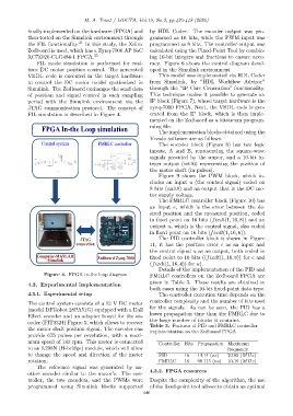
FIL simulation is described in Figure 4. erated from the IP block, which is then imple-
mented on the Zedbaord as a bitstream program-
ming file.
FPGA In-the Loop simulation The implementation blocks obtained using the
Vivado software are as follows:
Control system FMRLC controller The encoder block (Figure 8) has two logic
inputs, A and B, representing the square-wave
signals provided by the sensor, and a 16-bit in-
teger output (int16) representing the position of
the motor shaft (in pulses).
Figure 9 shows the PWM block, which in-
cludes an input u (the control signal) coded on
8 bits (unit8) and an output that is the DC mo-
tor supply voltage.
The FMRLC controller block (Figure 10) has
an input e, which is the error between the de-
sired position and the measured position, coded
in fixed point on 16 bits (fixdt(1, 16, 8)) and an
output u, which is the control signal, also coded
in fixed point on 16 bits (fixdt(1, 16, 6)).
JTAG The PID controller block is shown in Figure
connection 11, it has the position error e as an input and
the control signal u as an output, both coded in
Computer-MATLAB Zedboard Zynq-7000 fixed point to 16 bits ((fixdt(1, 16, 8)) for e and
/Simulink
(fixdt(1, 16, 4)) for u).
Details of the implementation of the PID and
Figure 4. FPGA in-the loop diagram FMRLC controllers on the Zedboard FPGA are
given in Table 3. These results are obtained in
4.3. Experimental implementation
both cases using the 16-bit fixed-point data type.
4.3.1. Experimental setup The controller execution time depends on the
controller complexity and the number of bits used
The control system consists of a 12 V DC motor
for the signals. As can be seen, the PID has a
(model DFRobot 28PA51G) equipped with a Hall
lower propagation time than the FMRLC due to
Effect encoder and an adapter board for the en-
the large number of blocks it contains.
coder (FIT0324) Figure 5, which allows to recover
Table 3. Features of PID and FMRLC controller
the motor shaft position signal. The encoder can
implementation on the Zedboard FPGA
provide 675 pulses per revolution, with a maxi-
mum speed of 143 rpm. This motor is connected Controller Bits Propagation Maximum
to an L298N (H-bridge) module, which will allow frequency
to change the speed and direction of the motor PID 16 14.14 (ns) 70.85 (MHz)
rotation. FMRLC 16 98.115 (ns) 10.19 (MHz)
The reference signal was generated by an-
4.3.2. FPGA resources
other encoder similar to the motor’s. The con-
troller, the two encoders, and the PWMs were Despite the complexity of the algorithm, the use
programmed using Simulink blocks supported of the fixed-point tool allows to obtain an optimal
440