
Page 72 - IJOCTA-15-3
P. 72
M. A. Touat / IJOCTA, Vol.15, No.3, pp.435-448 (2025)
D (t) = 0.52sin (t) (15)
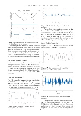
Figure 16. Position tracking error with PID
controller
Figure 15 shows a test with a reference varying
between 0.04 rad and 0.55 rad, generated by an
encoder similar to that of the DC motor. As can
be seen, the PID controller performs well, with
a short response time that quickly converges to
the desired reference signal. The tracking error is
about ±0.03 rad, as shown in Figure 16.
Figure 14. Simulation results of position tracking
5.2.2. FMRLC controller
with disturbances on the control
According to the simulation results obtained Figures 17 and 18 show the experimental results
in FIL mode (Figure 14), good tracking and good obtained with the FMRLC controller.
stability are observed. The proposed controller
shows good robustness despite the disturbance in-
jected into the control signal at time t = 20s. The
FMRLC controller manages to adapt to the refer-
ence changes and rejects the applied disturbance.
5.2. Experimental results
In this part, the experimental results obtained
during the position control of the DC motor us-
ing the Zedboard FPGA are presented. In order
to verify the efficiency of the proposed algorithm, Figure 17. Experimental results of position
the results obtained with the FMRLC controller tracking with FMRLC controller
were compared with those obtained with the PID
controller.
5.2.1. PID controller
The PID controller parameters were tuned using
the PID Tuner tool in Simulink. The parameters
obtained are as follows: P = 21, I = 1.9, and D
= 15. The experimental results obtained with the
PID controller are shown in Figures 15 and 16.
Figure 18. Position tracking error with FMRLC
controller
The generated setpoint varies between −0.9
and 0.9. Excellent tracking can be seen here. The
FMRLC controller closely tracks the reference sig-
Figure 15. Experimental results of position nal with a very short response time, as shown in
tracking with PID controller Figure 17. This is reflected in a tracking error of
444