
Page 71 - IJOCTA-15-3
P. 71
FPGA design and implementation of fuzzy learning control: Application on DC motor position control
VHDL code in terms of computation time and re- 5.1.1. FIL simulation with parametric
sources consumed by the FPGA circuit. 36,37 Ta- disturbances
ble 4 illustrates the hardware resources consumed In order to prove the efficiency and robustness of
when implementing the PID and FMRLC con- the proposed algorithm against parameter uncer-
trollers on the Zedboard, using a sample rate of
tainties, these parameters are varied in real-time
1 MHz. As we can see, the FMRLC control con-
simulation (see Table 5):
sumed 12.68% of LUTs (Look Up Table), 0.47% of
LUTRAMs (Memory LUT), 1.62% of FFs (Flip- Table 5. DC motor model parameter variations
Flop), 38.18% of DSPs (Digital Signal Processor),
6.00% of IOs (Input/Output), 6.38% of BUFGs Time t=8s t=15s t=23s t=32s
(Global Buffer) and 25.00% of MMCMs (Mixed- Dead zone
Parameter b 0 a 1 a 0
Mode Clock Manager). Value 10 2 2 [-3.1V 3.3V]
Table 4. FPGA resources consumption
Resource Available Utilization Utilization
(PID) (FMRLC)
LUT 53200 651(1.22%) 6801(12.68%)
LUTRAM 17400 39(0.22%) 81(0.47%)
FF 106400 664(0.62%) 1725(1.62%)
DSP 220 6(2.73%) 84(38.18%)
IO 200 12(6.00%) 12(6.00%)
BUFG 32 3(9.38%) 3(9.38%)
MMCM 4 1(25.00%) 1(25.00%)
5. Results
5.1. FIL simulation results
In this section, the results obtained by imple-
menting the proposed algorithm with FPGA in
the loop are presented in order to see the be-
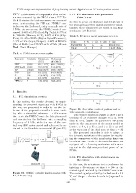
Figure 13. Simulation results of position tracking
havior of the proposed controller in case track-
with parametric disturbances
ing with a sinusoidal reference. In this execu- The results obtained in Figure 13 show a good
tion mode, the FMRLC controller is implemented tracking of the reference changes with an error
and executed on the Zedboard with a sampling close to zero, despite the parametric variations
frequency of 1 kHz, while the rest of the con- made on the parameters of the motor model at
trol loop (DC motor model and reference) is ex-
times t = 8 s, t = 15 s, and t = 23 s, as well
ecuted in the Simulink environment (Figure 12).
as the variation of the dead zone at time t = 32
s. The proposed controller is able to adapt to
the dynamic variations of the system by modify-
ing the parameters of the membership functions
in a short time, thanks to the controller structure
equipped with a learning mechanism with mem-
ory and to the high computational power of the
FPGA.
5.1.2. FIL simulation with disturbances on
the control
Zedboard Zynq-7000 In this case, the robustness test is performed by
injecting a disturbance at time t = 20s on the
control signal provided by the FMRLC controller.
Figure 12. FMRLC controller implementation with The control signal provided by the Zedboard is 3.3
FPGA In-the Loop V, and the perturbation formula is (expressed in
volts):
443