
Page 39 - JCTR-10-3
P. 39
Rando et al. | Journal of Clinical and Translational Research 2024; 10(3): 212-218 213
not uniformly effective for patients with massive or torrential tricuspid valve surface. The scanner generates a 3D model of the
FTR and/or those with significant leaflet tethering [2]. For these tricuspid valve by projecting light onto the valvular surface and
reasons, a novel surgical or percutaneous repair option that recording the pattern of light reflected back to the scanner. The
addresses these shortcomings would be of significant value. light distortions caused by the surface structures of the tricuspid
To test novel therapies for FTR, an ex vivo model of FTR is valve can be analyzed to generate a 3D point cloud. The point
needed. Unfortunately, the currently available ex vivo models cloud is then exported into a 3D scan-to-computer-aided design
of the tricuspid valve are costly, difficult to replicate, or have reverse engineering software (Geomagic, Morrisville, North
not been formally validated [3-8]. Our laboratory has previously Carolina, USA), which allows for visualization of the tricuspid
been successful in developing an ex vivo model of secondary valve as a 3D model and enables subsequent analysis of the
mitral regurgitation (SMR) using isolated porcine hearts [9]. valvular geometry (Figure 3).
Given the comparable tricuspid anatomy between humans
and swine [5-8,10] we hypothesized that porcine hearts could 2.3. Induction of FTR
similarly be used to develop a static ex vivo model of FTR. After imaging the tricuspid valve in its native state, the
2. Materials and Methods right atriotomy was closed with 4-0 prolene (Figure 2B).
Closure of the atriotomy was necessary to create a closed
2.1. Ex vivo model setup system that could sustain right ventricular pressure even after
the induction of FTR. Without this step, increases in right
Isolated porcine hearts were procured from an abattoir
(ATSCO, Inc, Plano, TX, USA), and any remaining pericardium ventricular pressure would result in leakage of air through the
tricuspid valve and loss of pressure in the right ventricle. The
was removed. The coronary arteries were ligated using a 2-0 silk right ventricular pressure was then increased from 30 mmHg to
suture, and the aorta and pulmonary artery were cross-clamped.
Cannulae were placed into the pulmonary artery and aorta through
purse string sutures and were advanced into the right ventricle and A B C
left ventricle, respectively. Pressurized air was delivered through
the cannulae using a 38-W linear-drive air pump (Thomas,
Gardner-Denver Medical, Sheboygan, WI, USA), and ventricular
pressure was maintained at 120 mmHg in the left ventricle, and
30 mmHg in the right ventricle. Static pressurization of the left
ventricle and right ventricle in such a manner results in the closure
of the mitral and tricuspid valves and allows for assessment of
valvular geometry (Figure 1). The right atrium was then opened
and the atrial tissue was retracted laterally to allow for subsequent
imaging and manipulation of the tricuspid valve (Figure 2A).
2.2. Image acquisition
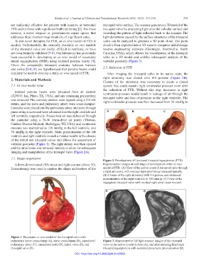
Figure 2. Development of functional tricuspid regurgitation (FTR).
A three-dimensional (3D) structured light scanner (Artec 3D, Representative images at each stage of development of the ex vivo
Luxembourg) was used to capture the shape and texture of the model of FTR. (A) View of the native (control) tricuspid valve through
a right atriotomy, with residual right atrial tissue retracted laterally.
(B) Closure of the right atriotomy with 4-0 prolene and sustained
pressurization of the right ventricle to 100 mmHg. (C) View of the
regurgitant tricuspid valve with residual right atrial tissue excised.
A B
Figure 1. Pneumatic ex vivo model of the tricuspid valve with
pulmonary artery cross-clamp (A), aortic cross-clamp (B), cannulated Figure 3. Representative 3D light scanner images of the tricuspid
pulmonary artery (C), cannulated aorta (D), mitral valve (E), and valve in the native (control) state (A), and after inducing functional
tricuspid valve (F). tricuspid regurgitation with sustained pneumatic pressurization (B).
DOI: https://doi.org/10.36922/jctr.24.00003