
Page 40 - MSAM-2-2
P. 40
Materials Science in Additive Manufacturing Tensile and fatigue properties of Ti6Al4V SLM parts
During parameter optimization process, high energy 4.2.2. Impact of build orientation on tensile property
density causes excessive melting of the layers and The tensile strengths of different build orientations are
balling . This happens when the molten metal does not compared. The UTS of the vertical specimens was higher
[31]
wet the substrate below due to surface tension, and hence than that of the horizontal specimens when specimens
results in balling. Therefore, high energy density does not were printed with 30-μm layer thickness. First, post-
necessarily increase the relative density of the material or processing is one of the key root causes. The horizontal
improve its quality. However, if the energy density is too specimens had supports when printed and they had to
low, the bond between each layer will not be good due to be removed by manual polishing tools. However, such
insufficient penetration depth . manual grinding may further propagate the poles or cracks
[32]
Scan patterns are used to determine if the metal nearby the surface, which bring negative impact to the
parts have an isotropic or anisotropic nature. Scanning sample’s mechanical properties. “Holes,” where the support
direction may be unidirectional or bidirectional (zigzag). structure used to be, were observed (Figure 4), which
Bidirectional prints are more efficient than unidirectional bring negative impact on the part property. Therefore, the
prints as there is less downtime for the laser beam . Stripe specimens could have been grinded better, or machining
[4]
patterns have parallel scan tracks with fixed spacing between should be done in future. For example, more tolerance can
adjacent tracks, also known has hatching distance . Each be added onto the side attached with support structures.
[33]
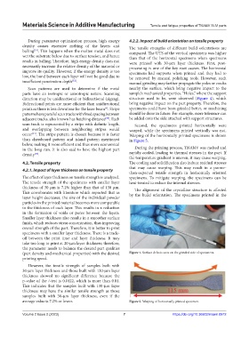
scan track is represented by a stripe with definite length, Second, the specimens printed horizontally were
and overlapping between neighboring stripes would warped, while the specimens printed vertically was not.
occur . The stripe pattern is chosen because it is faster Warping of the horizontally printed specimens is shown
[34]
than chessboard pattern and island pattern mentioned in Figure 5.
below, making it more efficient and thus more economical
in the long run. It is also said to have the highest part During the printing process, Ti6Al4V was melted and
[35]
density . rapidly cooled, leading to thermal stresses in the part. If
the temperature gradient is uneven, it may cause warping.
4.2. Tensile property The cooling and solidification also induce residual stresses
that may cause warping. This may result in a poorer-
4.2.1. Impact of layer thickness on tensile property
than-expected tensile strength in horizontally oriented
The effect of layer thickness on tensile strength is analyzed. specimens. To mitigate warping, the specimens can be
The tensile strength of the specimens with smaller layer heat-treated to reduce the internal stresses.
thickness of 30 μm is 7.2% higher than that of 130 μm. The alignment of the crystalline structure is affected
This corroborates with literature which reported that as by the build orientation. The specimens printed in the
layer height decreases, the size of the individual powder
particles in the printed material becomes more comparable
to the thickness of each layer. This results in a reduction
in the formation of voids or pores between the layers.
Smaller layer thickness also results in a smoother surface
finish, which reduces stress concentration, thus improving
overall strength of the part. Therefore, it is better to print
specimens with a smaller layer thickness. There is a trade-
off between the print time and layer thickness. It may
take too long to print at 20-μm layer thickness; therefore,
the parameter needs to balance the desired part qualities
(part density and mechanical properties) with the desired Figure 4. Surface defects seen on the grinded side of specimens.
printing speed.
However, the tensile strength of samples built with
30-μm layer thickness and those built with 130-μm layer
thickness showed no significant difference because the
p-value of the t-test is 0.0422, which is more than 0.01.
This indicates that the samples built with 130-μm layer
thickness may have the similar tensile strength as those
samples built with 30-μm layer thickness, even if the
average value is 7.2% or lower. Figure 5. Warping of horizontally printed specimen.
Volume 2 Issue 2 (2023) 7 https://doi.org/10.36922/msam.0912