
Page 37 - MSAM-2-2
P. 37
Materials Science in Additive Manufacturing Tensile and fatigue properties of Ti6Al4V SLM parts
testing machine. Tensile loading graphs can be obtained
from the software. Various properties such as true stress
and true strain can be obtained as well.
Other properties such as the elastic modulus (E), yield
stress at 0.2% of elongation (σ y), UTS and % elongation at
point of fracture was derived from the stress-strain curves
after the raw data were obtained. Stress-strain curves for
each specimen were used to understand the effects of the
three process parameters on tensile strength.
2.4. Fatigue property measurements
Fatigue testing was performed according to ASTM E466
standard with Shimadzu Servo-Pulser Fatigue Test
[30]
Machine. All the tests were performed in the ambient air
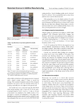
Figure 3. Comparison of non-sandblasted (top 3 pieces) and sandblasted condition. The testing coupon was designed in accordance
(bottom 3 pieces) specimens. with ASTM E466 guidelines. L = 210 mm, B = 25 mm,
b = 10 mm, L0 = 7 mm, and thickness = 3.5 mm. Cycle
Table 2. Specifications of specimens printed for tensile frequency used is 10 Hz.
testing
Ti-6Al-4V produced by SLM for the experiment has
Specimens Parameters several inherent microstructural defects, which reduce
Layer Build Post‑processing the fatigue strength. These defects should be noted while
thickness orientation conducting the experiment and computing the results.
130-H-N 130 μm Horizontal Non-sandblasted Caution was exercised when loading the specimen
130-H-SB 130 μm Horizontal Sandblasted to ensure that it was in the middle of both grips. This
130-V-N 130 μm Vertical Non-sandblasted prevented any bending stresses due to asymmetrical
130-V-SB 130 μm Vertical Sandblasted loading and reduced the vibrations during the fatigue
30-V-N 30 μm Vertical Non-sandblasted tests especially at high loads. The specimens received were
30-V-SB 30 μm Vertical Sandblasted warped both in the horizontal and vertical axes. Extra effort
30-H-N 30 μm Horizontal Non-sandblasted was needed to “straighten” the specimen using an F-clamp
so that the upper clamp would not knock the specimen
30-H-SB 30 μm Horizontal Sandblasted when being lowered. Aligning the specimen such that it
30-F-N 30 μm Flat Non-sandblasted was perpendicular to the clamps was a challenge due to
30-F-SB 30 μm Flat Sandblasted the warp. For this, effort was put into aligning the gauge
Notes: “H” stands for the horizontal part printing orientation; length perpendicular to the clamps instead of the ends of
“V” stands for the vertical part printing orientation; “F” stands for the the specimen.
flat part printing orientation; “N” stands for no sandblasting applied;
“SB” stands for sandblasting applied onto parts 2.5. Microstructure analysis
of the width and thickness of the gauge area were measured Microscopy was carried out to observe the fractured
with a digital vernier caliper 3 times to record the surface, where crack initiation points could be observed
average. The measured dimension instead of the designed to identify the cause of the fracture be it cracks, pores,
dimension was used in this case because of the error in or other defects. On the micro scale, beach lines and
printing, especially after the supports were grinded off. striations could be observed to identify the propagation
of the fatigue before the fracture. Types of microscopies
The tensile tests were conducted using the INSTRON used are optical microscopy, laser scanning microscope,
5569 testing machine with a load cell of 50 kN and a and scanning electron microscope. Observation of crack
crosshead speed of 0.015 mm/min. A clip-on 10-mm propagation was conducted with Optical Microscope
extensometer was attached to the middle section of the Olympus SZX16, Laser Scanning Microscope LEXT
specimen to measure the elongation at the gauge area. OLS4100, and Scanning Electron Microscope JEOL
Bluehill universal was the software used to calibrate the raw 5600LV. Surface quality was evaluated with Keyence Laser
data and graphs that was connected to the INSTRON 5569 Scanning Microscope.
Volume 2 Issue 2 (2023) 4 https://doi.org/10.36922/msam.0912