
Page 49 - MSAM-2-2
P. 49
Materials Science in Additive Manufacturing Biomimetic structures for optical focusing
A
B
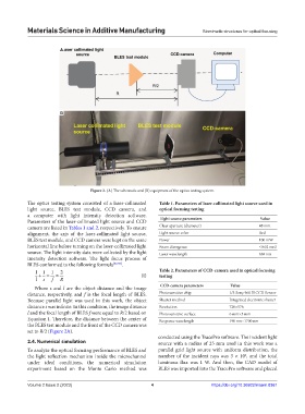
Figure 2. (A) The schematic and (B) equipment of the optics testing system.
The optics testing system consisted of a laser-collimated Table 1. Parameters of laser‑collimated light source used in
light source, BLES test module, CCD camera, and optical focusing testing
a computer with light intensity detection software.
Parameters of the laser-collimated light source and CCD Light source parameters Value
camera are listed in Tables 1 and 2, respectively. To ensure Clear aperture (diameter) 48 mm
alignment, the axis of the laser-collimated light source, Light source color Red
BLES test module, and CCD camera were kept on the same Power 100 mW
horizontal line before turning on the laser-collimated light Beam divergence ≤0.02 mrd
source. The light intensity data were collected by the light Laser wavelength 638 nm
intensity detection software. The light focus process of
BLES conformed to the following formula [32,33] .
11 1 2 (I) Table 2. Parameters of CCD‑camera used in optical focusing
testing
l s f R
CCD‑camera parameters Value
Where s and l are the object distance and the image
distance, respectively, and f is the focal length of BLES. Photosensitive chip 1/3 Sony 960 H CCD Sensor
Because parallel light was used in this work, the object Shutter method Integrated electronic shutter
distance s was infinite. In this condition, the image distance Resolution 720×576
l and the focal length of BLES f were equal to R/2 based on Photosensitive surface 6 mm×5 mm
Equation I. Therefore, the distance between the center of Response wavelength 190 nm~1700 nm
the BLES test module and the front of the CCD camera was
set to R/2 (Figure 2A).
conducted using the TracePro software. The incident light
2.4. Numerical simulation source with a radius of 25 mm used in this work was a
To analyze the optical focusing performance of BLES and parallel grid light source with uniform distribution, the
6
the light reflection mechanism inside the microchannel number of the incident rays was 3 × 10 , and the total
under ideal conditions, the numerical simulation luminous flux was 1 W. And then, the CAD model of
experiment based on the Monte Carlo method was BLES was imported into the TracePro software and placed
Volume 2 Issue 2 (2023) 4 https://doi.org/10.36922/msam.0361