
Page 61 - MSAM-2-2
P. 61
Materials Science in Additive Manufacturing Cellulose microfiber in ABS filament for 3D printing
increased surface area favors mixing with microfibers.
After grinding (in a knife mill), the material was divided
into two equal masses. One in which pure ABS filaments
will be produced and the other in which crystalline
cellulose microfiber will be added. The ABS was spiked
with 0.5% (in weight) of crystalline cellulose microfibers.
An extruder with a pulling mechanism was used to
produce pure and additived ABS filaments (Figure 5).
After the polymer extrusion, the material was cooled
by a channel ventilation system and pulled to form the
filament that is wound on a spool. The filament thickness
was 1.75 mm in diameter with a tolerance of ± 0.05 mm
ensured by dial gauge.
3.3. Conformation of the test specimens by FFF
Figure 4. Micrograph showing the morphology of cellulose microfiber.
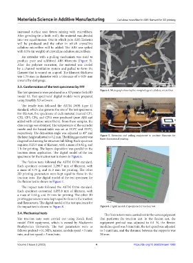
The test specimens were produced in a 3D printer Sethi3D
model S3. Test specimens’ digital models were prepared
using Simplify 3D software.
The tensile tests followed the ASTM D638 (type 1)
standard, which also governs the size of the test specimens.
For this test, five specimens of each material (named CP1,
CP2, CP3, CP4, and CP5) were produced (pure ABS and
added with cellulose microfibers). From these samples, the
data average was obtained. The temperature of the extruder
nozzle and the heated table was set at 115°C and 235°C,
respectively. The deposition angle was adjusted to 45° and
the layer height adjusted to 0.2 mm. The filling geometry was Figure 5. Extrusion and pulling equipment to produce filaments for
three-dimensional printing.
diagonal and aiming for structure full filling. Each specimen
requires 3525.9 mm of filament, with a mass of 8.82 g, and
1 h for printing. The layers deposition was parallel to the
traction stress application. The digital model of the test
specimens for the traction test is shown in Figure 6.
The flexion tests followed the ASTM D790 standard.
Each specimen consumed 2,298.7 mm of filament, with
a mass of 5.75 g, and 21.5 min for printing. The other
3D printing parameters were kept equal to those in the
traction tests. The digital model of the test specimen for
the flexion test is shown in Figure 7.
The impact tests followed the ASTM D256 standard.
Each specimen consumed 1,055.8 mm of filament, with
a mass of 2.64 g, and 19 min for printing. The other 3D
printing parameters were kept equal to those in the traction
and flexion tests. The digital model of the test specimen for
the impact test is shown in Figure 8. Figure 6. Digital model of specimens for traction test.
3.4. Mechanical tests The flexion tests were carried out in the same equipment
The traction tests were carried out using Zwick Roell that performs the traction test. In the flexion test, the
model Z100 equipment, which is owned by Mackenzie equipment preload was adjusted to 0.1 N, the flexion
Presbyterian University. The test parameters were as modulus speed was 5 mm/min, the test speed was adjusted
follows: preload = 0.1 MPa, tension module speed = 5 mm/ to 5 mm/min, and the distance between the supports was
min, and test speed = 5 mm/min. 50 mm.
Volume 2 Issue 2 (2023) 4 https://doi.org/10.36922/msam.1000