
Page 128 - MSAM-2-3
P. 128
Materials Science in Additive Manufacturing Powder alteration caused by L-PBF process
Figure 1. Particle-size distribution samples collected in different positions Figure 3. Four concentric cylinders with increasing distance spacing.
(matrix) over the build plate.
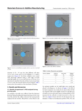
Figure 4. Lattices with different cell sizes.
Figure 2. Particle-size distribution samples relative to position of printed
cylinder.
Table 2. Lattice dimension parameters
diameter of Ø = 50 mm but four different cell sizes:
Volume
2 mm, 3 mm, 4 mm, and 5 mm for cylinders 1, 2, 3, and 4, Lattice cylinder Cell size Area ratio, ratio, R
R
C (mm)
respectively (Figure 4). The lattice cylinders were created A V
with nTopology software using a cube edge structure 1 2 8.4 0.49
with fillet radius of 2.1 mm and thickness of 0.5 mm. It is 2 3 5.7 0.42
important to note that when the cell size was increased from 3 4 3.6 0.26
2 mm to 5 mm, the area and volume ratios dropped. Table 2 4 5 2.4 0.18
presents the characteristics of the four lattice cylinders.
3. Results and discussion the unfused powder on the build plate were sieved and
placed in the dispenser. As shown in Figure 5, the PSD of
3.1. Results of experiment 1: PSD analyzed during the three samples is very similar, but it can be observed that
printing cycle the dispenser PSD moves slightly to the left in the direction
Two samples of powder were collected from the dispenser of smaller particles after printing and sieving, while the PSD
before printing, two after printing and sieving, and two more measured in the collector is located between the other two
from the collector bin, which contained the excess powder PSD arcs. Figure 6 shows that after the sieving process, the
displaced by the recoater. The powder in the collector and diameter D-values of the dispenser powder D90, D50, and
Volume 2 Issue 3 (2023) 5 https://doi.org/10.36922/msam.1781