
Page 9 - MSAM-3-3
P. 9
Materials Science in Additive Manufacturing Multi-material Ti6Al4V-B4C through L-DED
A B a rapid turn lathe unit. The diameter was reduced until
a cemented carbide-cutting insert removed the rough
as-printed exterior. Subsequently, the sample was turned
to height using a parting tool to remove both ends of the
cylinder based on a height-to-diameter ratio of 1.5 – 2 with
the end sample appearance in Figure 1C. Turning of the
Ti64 cylinders was performed swiftly without damaging
the cutting insert, whereas the treated samples were cut
slowly with higher RPM, lower cut depths, and slower feed
C D speeds.
2.2. Microstructural characterization and phase
analysis
A low-speed diamond saw was used to cut an
unmachined sample into three sections to characterize
its microstructure. The top of the cylinder was sectioned
first in the build plane, as seen in Figure 1D; the rest was
cut along the axis. Thus, the sample’s circular and side
E F cross-sections were exposed. All three sample sections
were then mounted into one phenolic resin, ground
sequentially using 80 – 1200 SiC grit-size grinding papers,
and polished with alumina particles (of decreasing particle
size, i.e., 1 – 0.05 µm) dispersed in deionized water. Kroll’s
reagent was used to etch the samples by dipping them in
the etchant for 30 s and washing them off using deionized
water. The microstructures were acquired using a Keyance
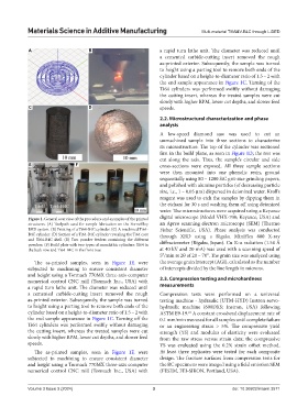
Figure 1. General overview of the procedure and examples of the printed digital microscope (Model VHX-700; Keyance, USA) and
structures. (A) Toolpath used for sample fabrication on the FormAlloy an Apreo scanning electron microscope (SEM) (Thermo
DED system. (B) Printing of a Ti64-B4C cylinder. (C) A machined Ti64- Fisher Scientific, USA). Phase analysis was conducted
B4C cylinder. (D) Section of a Ti64-B4C cylinder revealing the Ti64 core through XRD using a Rigaku MiniFlex 600 X-ray
and Ti64-B4C shell. (E) Two powder feeders containing the different
powders. (F) Build plate with two types of monolithic cylinders: Ti64 in diffractometer (Rigaku, Japan). Cu K-α radiation (1.54 Å
the back row and Ti64-B4C in the front row. at 40 kV and 20 mA) was used with a scanning speed of
5°/min at 2θ of 20 – 70°. The grain size was analyzed using
The as-printed samples, seen in Figure 1F, were the average grain intercept (AGI), calculated as the number
subjected to machining to ensure consistent diameter of intercepts divided by the line length in microns.
and height using a Tormach 770MX three-axis computer
numerical control CNC mill (Tormach Inc., USA) with 2.3. Compression testing and microhardness
a rapid turn lathe unit. The diameter was reduced until measurements
a cemented carbide-cutting insert removed the rough Compression tests were performed on a universal
as-printed exterior. Subsequently, the sample was turned testing machine - hydraulic (UTM-HYD) Instron servo-
to height using a parting tool to remove both ends of the hydraulic machine (600DXS; Instron, USA) following
cylinder based on a height-to-diameter ratio of 1.5 – 2 with ASTM E9-19. A constant crosshead displacement rate of
21
the end sample appearance in Figure 1C. Turning off the 0.1 mm/min was used for all samples until complete failure
Ti64 cylinders was performed swiftly without damaging or an engineering strain > 5%. The compressive yield
the cutting insert, whereas the treated samples were cut strength (YS) and modulus of elasticity were evaluated
slowly with higher RPM, lower cut depths, and slower feed from the raw stress versus strain data; the compressive
speeds. YS was evaluated using the 0.2% strain offset method.
The as-printed samples, seen in Figure 1F, were At least three replicates were tested for each composite
subjected to machining to ensure consistent diameter design. The fracture surfaces from compression tests for
and height using a Tormach 770MX three-axis computer the RC specimens were imaged using a field emission SEM
numerical control CNC mill (Tormach Inc., USA) with (FESEM, FEI-SIRON, Portland, USA).
Volume 3 Issue 3 (2024) 3 doi: 10.36922/msam.3571