
Page 14 - MSAM-3-3
P. 14
Materials Science in Additive Manufacturing Multi-material Ti6Al4V-B4C through L-DED
A C D
E
B
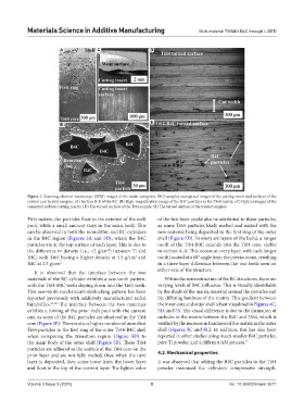
Figure 7. Scanning electron microscope (SEM) images of the radial composite (RC) samples and optical images of the cutting insert and surfaces of the
control and treated samples. (A) Section B-B of the RC. (B) High-magnification image of the B4C particles in the Ti64 matrix. (C) Optical images of the
cemented carbide-cutting inserts. (D) The turned surface of the Ti64 sample. (E) The turned surface of the treated samples.
Ti64 matrix, the particles float to the exterior of the melt of the first layer could also be attributed to these particles,
pool, while a small amount stays in the main body. This as some Ti64 particles likely melted and mixed with the
can be observed in both the monolithic and RC cylinders new material being deposited in the first ring of the outer
in the B4C region (Figures 3A and 5D), where the B4C shell (Figure 5D). In every six layers of the build, a longer
particles are at the top surface of each layer. This is due to tooth of the Ti64-B4C extends into the Ti64 core, visible
the difference in density (i.e., <2 g/cm ) between Ti and in section A-A. This occurs at every layer, with each longer
3
B4C, with Ti64 having a higher density at 4.5 g/cm and tooth located at a 60° angle from the previous one, resulting
3
B4C at 2.5 g/cm . in a three-layer difference between the two teeth seen on
3
It is observed that the interface between the two either side of the structure.
materials of the RC cylinder exhibits a saw-tooth pattern, Within the microstructure of the RC structures, there are
with the Ti64-B4C teeth sloping down into the Ti64 teeth. varying levels of B4C influence. This is visually identifiable
This saw-tooth mechanical-interlocking pattern has been by the shade of the matrix material around the particles and
reported previously with additively manufactured radial the differing hardness of the matrix. This gradient between
bimetallics. 11,12 The interface between the two materials the inner core and outer shell is best visualized in Figures 4C,
exhibits a mixing of the prior melt pool with the current 5D, and 7A. The visual difference is due to the formation of
one, as some of the B4C particles are observed in the Ti64 carbides in the matrix between the B4C and Ti64, which is
core (Figure 5F). There is also a higher number of unmelted verified by the increase in hardness of the matrix in the outer
Ti64 particles in the first ring of the outer Ti64-B4C shell shell (Figures 5C and 8C). In addition, this has also been
when comparing the transition region (Figure 5D) to reported in other studies using much smaller B4C particles,
the main body of the outer shell (Figure 5B). These Ti64 pure Ti powder, and a different AM process. 15
particles are adhered to the surface of the Ti64 core on the
prior layer and are not fully melted; thus, when the next 4.2. Mechanical properties
layer is deposited, they come loose from the lower layer It was observed that adding the B4C particles to the Ti64
and float to the top of the current layer. The lighter color powder increased the cylinders’ compressive strength,
Volume 3 Issue 3 (2024) 8 doi: 10.36922/msam.3571