
Page 95 - MSAM-3-3
P. 95
Materials Science in Additive Manufacturing Wide-angle broadband MMA with CB-CIP/PLA
At an incident angle of 50°, the bandwidth is 12.46 GHz. To further analyze the impedance matching performance
Therefore, the SSH structure maintains good absorption of the SSH absorber, 42,43 the effective input impedance (Z )
eff
properties even when the incident angle changes in the TE of the structure was calculated,
and TM polarization modes.
2
(1 + S ) − S 2
3.5. Absorption mechanism Z eff = 11 2 21 (V)
2
11
The absorption mechanism of the designed SSH (1 − S ) − S 21
structure was analyzed. Good impedance matching of the where S is the reflection coefficient and S is the
11
21
structure is essential for effective broadband microwave transmission coefficient. An SSH structure is formed in a
attenuation. The impedance matching (Z) and attenuation process of material reduction by cutting holes layer-by-layer
constant (α) can be calculated as follows: 40,41 into a solid block to create gradient effects. The Z of the
eff
solid block was also calculated for comparison (Figure 11).
Z
Z = in = r + jx (III) For the SSH structure, there are large fluctuations of Z in
eff
Z 0 the frequency range of 2 – 4.75 GHz, and the impedance
mismatch leads to poor absorption in this frequency range.
The real and imaginary parts of Z in the frequency range
eff
2
’’
’
’
’’
2 π f ( µε − µε ) of 4.75 – 18 GHz become close to 1 and 0, respectively,
’’
’
’
’’
α = ( µε − µε ) + indicating a good impedance match between the SSH
c +( µε + µε ) 2 (IV) structure and free space in this frequency range. In the
’
’’
’’
’
solid block, the real and imaginary parts of Z fluctuate
eff
where the real part r is the resistance, and the imaginary greatly in the frequency range of 2 – 18 GHz, preventing
part x is the reactance, which includes the capacitive and effective wave absorption in this range. The SSH structure
inductive reactance. The impedance matching of absorbing improves the impedance matching between the structure
materials should generally exceed 0.3. A higher Z-value, and free space through the gradient effect of layer-by-
e.g., close to 1, suggests better impedance matching of layer opening holes. The large square hole at the top of
the material. The incident wave can better transmit into the SSH structure allows more electromagnetic waves to
the material, thus reducing the reflection on the surface enter the structure smoothly. Once electromagnetic waves
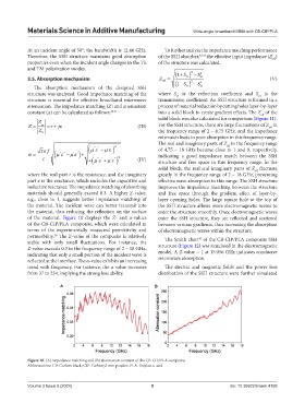
of the material. Figure 10 displays the Z- and α-values enter the SSH structure, they are reflected and scattered
of the CB-CIP/PLA composite, which were calculated in between various gradients, thus increasing the absorption
terms of the experimentally measured permittivity and of electromagnetic waves within the structure.
permeability. The Z-value of the composite is relatively The Smith chart of the CB-CIP/PLA composite SSH
38
43
stable with only small fluctuations. For instance, the structure (Figure 12) was simulated in the electromagnetic
Z-value exceeds 0.3 in the frequency range of 2 – 18 GHz, model. A Z-value = 1 at 15.056 GHz indicates conducive
indicating that only a small portion of the incident wave is
reflected at the interface. The α-value exhibits an increasing microwave absorption.
trend with frequency. For instance, the α value increases The electric and magnetic fields and the power loss
from 37 to 234, implying the strong loss ability. distribution of the SSH structure were further simulated
A B
Figure 10. (A) Impedance matching and (B) attenuation constant of the CB-CIP/PLA composite
Abbreviations: CB: Carbon black; CIP: Carbonyl iron powder; PLA: Polylactic acid
Volume 3 Issue 3 (2024) 8 doi: 10.36922/msam.4158