
Page 92 - MSAM-3-3
P. 92
Materials Science in Additive Manufacturing Wide-angle broadband MMA with CB-CIP/PLA
A B
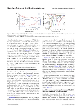
Figure 5. (A) Measured permittivity (ε) and permeability (μ) of the CB-CIP/PLA composite. (B) Calculated reflection loss of the composite absorber with
different thicknesses in the frequency range of 2 – 18 GHz
Abbreviations: CB: Carbon black; CIP: Carbonyl iron powder; PLA: Polylactic acid; Im: imaginary part; Re: real part
where Z is the impedance of free space (≈377 Ω), Z is 1.6 mm at an interval of 0.2 mm, the frequencies for the
0
in
the input impedance of a composite plate absorber, ε and peak values of RL tend to slightly decrease. Similarly, the
r
μ are the relative complex permittivity and permeability, absorption peak values for LF and medium frequencies
r
respectively, f is the frequency of the incident microwave, decrease, while the peak values for HF increase. When W
d is the thickness of the absorbing material plate, and c is increases from 1.0 to 1.4 mm, the maximum RL increases
the velocity of the electromagnetic wave in free space from −35.52 to −44.53 dB but at different frequencies.
(c = 3 × 10 m/s). As displayed in Figure 5B, thickness has a Increasing W reduces the width of the structural resonance
8
significant influence on the RL intensity and peak position. between the different cells, thus deteriorating reflective
With increasing thickness, the peak value of RL tends to intensity at corresponding frequencies. The −10 dB
occur at a lower frequency. This phenomenon could be absorption bandwidth at W = 1.4 mm is 14.032 GHz.
explained by the quarter-wavelength cancellation theory
(λ/4). However, the EAB of the single-layer CB-CIP/PLA Figure 6C displays the RL of SSH structures with
composite becomes relatively narrow with increased different height H values. As H increases from 16 to
thickness. Note that the EAB in microwave absorbers 22 mm, the absorption bandwidth increases gradually.
is defined by the frequency range corresponding to When H varies from 8 to 14 mm with an interval of 2 mm,
1
RL < −10 dB. 38 the absorption peak first increases and then decreases at
different frequencies (Figure 6D). When H = 12 mm, the
1
3.2. Effect of geometric parameters of the SSH absorption peak value is the maximum, and the absorption
structure on microwave absorption performance bandwidth is 14.032 GHz. As indicated in Figure 6E, the
To achieve wide-angle, broadband, and strong microwave effect of H on absorption intensity is low, especially for LF
2
absorption, the geometric parameters were optimized and medium frequencies.
by electromagnetic simulation. Figure 6A displays the Given both the absorption bandwidth and absorption
RL of SSH structures as a function of R at W = 1.4 mm, peak value, the combined geometric parameters for the SSH
H = 18 mm, H = 12 mm, and H = 6 mm. There are MMA structure are R = 12 mm, W = 1.4 mm, H = 18 mm,
1
2
almost three absorption peaks in each RL curve in the H = 12 mm, and H = 6 mm; and they were selected for
1
2
frequency range of 2 – 18 GHz. As the R increases, the printed samples used in subsequent experiments. With
low-frequency (LF) and medium-frequency absorption these optimal parameters, the maximum absorption
peaks gradually shift to the right, while the high- intensity of the structure occurs at the frequency of 15.056
frequency (HF) absorption peaks shift to the left. The GHz (Figure 6E).
peak values increase with R. When R is increased to
12 mm, the −10 dB absorption bandwidth is 14.032 GHz, 3.3. Microwave absorption performance of the SSH
covering all X and Ku bands. However, a further increase structure at different polarization angles
in R leads to less effective microwave absorption with Polarization characteristics of the SSH structure were
decreased bandwidth. analyzed using the electromagnetic simulation. Figure 7
Figure 6B demonstrates the effect of W on the RL of displays the influence of polarization angle on the
SSH structures. As the thickness W increases from 1.0 to absorption properties with electromagnetic waves at
Volume 3 Issue 3 (2024) 5 doi: 10.36922/msam.4158