
Page 90 - MSAM-3-3
P. 90
Materials Science in Additive Manufacturing Wide-angle broadband MMA with CB-CIP/PLA
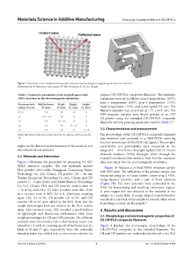
Figure 1. Schematic of the metamaterial absorber structure and the designed stepped square hole unit within it
Abbreviations: R: Maximum hole radius; W: Wall thickness; H, H , H : Height
1 2
Table 1. Geometric parameters of the stepped square hole prepare CB-CIP/PLA composite filaments. The extrusion
(SSH) structure in the electromagnetic simulation parameters were set as follows: zone 1 temperature: 145°C;
zone 2 temperature: 165°C; zone 3 temperature: 175°C;
Maximum hole Wall thickness, Height Height, Height,
radius, R (mm) W (mm) H (mm) H (mm) H (mm) head temperature: 175°C; and screw speed: 18 rpm. The
1 2 filament diameter was controlled at 1.75 ± 0.05 mm. The
8–16 1.4 18 12 6 SSH structure samples were finally printed in an FFF
12 1.0 – 1.6 18 12 6 3D printer using the extruded CB-CIP/PLA composite
12 1.4 16 – 22 12 6 filaments with the printing parameters listed in Table 2. 38
12 1.4 18 8 – 14 6
12 1.4 18 12 2 – 8 2.3. Characterization and measurement
Note: The sweep interval is 2 mm for R, H, H , and H ; and 0.2 mm for The morphology of the CB-CIP/PLA composite filaments
1
2
W. was observed and analyzed in a JSM-IT500 scanning
electron microscope (SEM; JEOL Ltd, Japan). The complex
angles on the absorption performance of the structure was permittivity and permeability were measured in the
also simulated and analyzed. range of 2 – 18 GHz in a Keysight Agilent E5071C Vector
Network Analyzer (VNA; Keysight, USA) through the
2.2. Materials and fabrication
coaxial transmission line method. Note that the measured
Figure 2 illustrates the procedure for preparing the SSH data were input into the electromagnetic simulation.
MMA structure samples. The raw materials include Figure 3A features a printed MMA structure sample
PLA powder (250 mesh; Dongguan Huachuang Plastic with SSH units. The reflectivity of the printed sample was
Technology Co. Ltd., China), CB powder (30 – 40 nm; measured using an in-house system comprising a VNA,
Tianjin Zhengyuan Technology Co. Ltd., China), and CIP wedge-tapered absorber, and a pair of horn antennas
powder (1 – 5 µm; Hebei Lebo Metal Material Technology (Figure 3B). The horn antennas were connected to the
Co. Ltd., China). PLA and CB (specific surface area: 55 VNA for transmitting and receiving microwave signals.
– 70 m /g; resistivity: 2.5 Ωm) powders were first dried A pure copper foil was attached to the backside of the
2
in a vacuum oven at 80°C for 6 h. Aluminate coupling sample as a metal plate. A wedge-shaped conical absorber
agent (AL; 1.5 wt.%), CB powder (20 wt.%), and CIP was fitted to the back of the sample to prevent other waves
powder (30 wt.%) were added to the PLA. Note that the from being incident on the sample. 36
weight percentages here are relative to the PLA matrix
mass. Our previous study [38] revealed a good balance 3. Results and discussion
of lightweight and absorption performance with these
weight percentages for CB and CIP powders. The different 3.1. Morphology and electromagnetic properties of
powders were then loaded into a dual-motion mixer and CB-CIP/PLA composite filaments
mixed for 1 h with the rotating speed of the barrel and the Figure 4 displays the microscopic morphology of the
blade at 28 and 17 rpm, respectively. Next, the uniformly CB-CIP/PLA composite in the extruded filaments. The
mixed powder was added into a twin-screw extruder to CB and CIP particles are uniformly distributed in the PLA
Volume 3 Issue 3 (2024) 3 doi: 10.36922/msam.4158