
Page 13 - manuscript_ijb05583
P. 13
Results & Discussion
Sorting device design and characterization
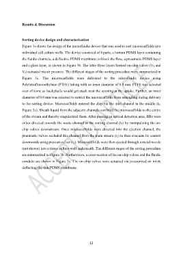
Figure 3a shows the design of the microfluidic device that was used to sort microscaffolds into
individual cell culture wells. The device consisted of 4 parts, a bottom PDMS layer containing
the fluidic channels, a deflective PDMS membrane to block the flow, a pneumatic PDMS layer
and a glass layer, as shown in Figure 3b. The latter three layers formed on-chip valves (V1 and
V2) actuated via air pressure. The different stages of the sorting procedure were summarized in
Figure 3c. The microscaffolds were delivered to the microfluidic device using
Polytetrafluoroethylene (PTFE) tubing with an inner diameter of 0.8 mm. PTFE was selected
over silicone as buckyballs would get stuck near the opening at the uptake. Further, an inner
diameter of 0.8 mm was selected to restrict the microscaffolds from entangling during delivery
to the sorting device. Microscaffolds entered the chip via the inlet channel in the middle (t0,
Figure 3c). Sheath liquid from the adjacent channels confined the microscaffolds to the centre
of the stream and thereby singularized them. After passing an optical detection area, BBs were
either directed towards the waste channel or the sorting channel (t1) by manipulating the on-
chip valves downstream. Once microscaffolds were directed into the ejection channel, the
pneumatic valves secluded this channel from the main stream (t2) to then evacuate its content
downwards using pressurized air (t3). Microscaffolds were then ejected through a metal nozzle
(not shown) into a tissue culture well underneath. The different stages of the sorting procedure
are summarized in Figure 3b. Furthermore, a cross-section of the on-chip valves and the fluidic
conduits are shown in Figure 3c. The on-chip valves were actuated via pressurized air inlets
deflecting the thin PDMS membrane.
12